
 FR
FR 
The relationship between structural works and special foundations relies largely on the Load Transfer Document (LTD), which, beyond a simple listing, can play a truly structuring role in the project design and in defining the interface between trades.
When advantageously supplemented with information such as execution tolerance management and the stiffness to consider at the top of each pile, the LTD becomes a key element — relayed by the technical specifications (STS) — to clarify the boundary between trades and secure the design.
This article provides specific insight into these sometimes‑confusing geometric, mechanical, and contractual aspects, and shows the value of documenting them early on.
- Pile Execution Tolerances
- Structural Design Drawings by the Design Team
- Project‑Specific Contract Documents
- Structural Design on Piles
- Summary in the Form of an Example
Pile Execution Tolerances
In France, the execution standards for piles allow by default construction tolerances that are relatively favourable to special‑foundations contractors:
- NF EN 1536, which concerns bored piles, provides:
- 10 cm in plan position
- 2 cm/m in inclination
- NF EN 12699, which concerns driven piles, provides:
- 10 cm in plan position
- 4 cm/m in inclination
- The informative NF P94‑262, used when the pile technology is not fixed, provides by default:
- 15 cm in plan position
- 3 cm/m in inclination
Furthermore, these tolerances apply from the working platform used by the piling machine. As a result, the inclination deviation can increase the plan‑position deviation when piles are installed before final excavation, from a high platform.
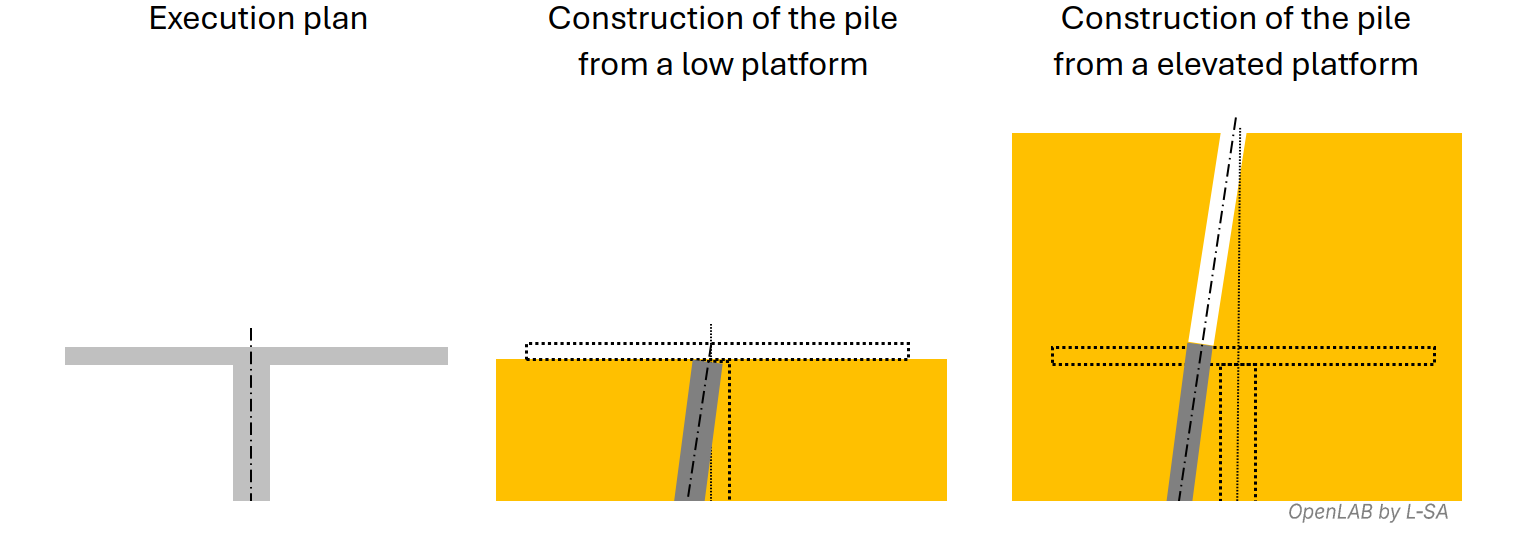
This high‑platform configuration can occur during the construction of retaining walls (secant piles, tangent piles, spaced piles, soldier‑pile walls…), or more generally when access, sequencing, or schedule constraints prevent the piling rig from descending into the excavation.
Structural Design Drawings by the Design Team
Plan‑position and inclination deviations are part of construction reality; considering them from the design stage contributes to the robustness of the structure.
From a geometric standpoint, identifying the fixed dimensions in the drawings and providing the architect with the correct clearances and dimensional allowances will ensure compliance of the structure, provided the piles themselves comply with tolerances.
Structural drawings created using nominal dimensions without analysing tolerance effects can lead to problematic situations on site: piles crossing property lines, non‑compliant internal dimensions (parking space depth, roadway width, etc.). Anticipating these issues reduces such risks.
These deviations may also be magnified by load‑induced deformations of special foundations—sometimes several centimetres in service (pile‑head displacement, top or mid‑height wall deformation, etc.).
In particular, the elevation—previously mentioned—of the future working platform for the piling contractor is one of the key assumptions the structural design office must know and define to fulfil its design role and prepare the tender documents.
Project‑Specific Contract Documents
Tightening of Execution Tolerances
The special‑foundations contract documents may, when necessary, specify stricter normative tolerances than those previously mentioned, within reasonable limits (NF P94‑262 R.1(2) and R.3(5)).
“Assigning Responsibility” to the Special Foundations Package
The contract documents may also state that the piles shall absorb the effects resulting from their own plan‑position and inclination tolerances.
The design office then translates this design choice into the ULS load transfer provided to the special‑foundations engineer.
Note: The effects of geometric imperfections are in principle ignored at SLS according to P94‑262 R.1.(5), and more generally EC2 §5.2 2(P) and §5.2(3).
It is difficult and risky to establish general rules, but except for small‑diameter piles, it is sometimes simpler to assign piles the responsibility to absorb the effects of their own tolerances:
- centrically loaded piles are designed axisymmetrically and can easily accommodate tolerances in all directions,
- they are often dimensioned by SLS in diameter and therefore have “reserve” capacity at ULS,
- the effects of horizontal forces and moments at the pile head remain localized and dissipate a few metres below the surface.
Conversely, the supported structures are usually designed at ULS and are rarely axisymmetric. Integrating pile tolerances in all possible directions may be more globally costly for the project.
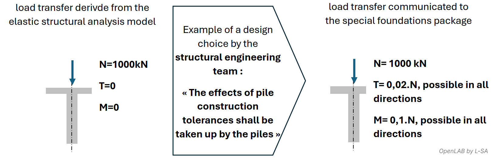
In the load‑transfer document, instead of directly pre‑calculating imperfection effects, a formula using relations such as (M = 0.1N…) or a generic mention clarifies assumptions and prevents the special‑foundations engineer from combining unrealistic load cases (e.g. {Nmin and M = 0.1Nmax}) or, conversely, omitting certain directions of imperfection.
This design choice — assigning piles the responsibility for the effects of their own tolerances — should also be explicitly stated in the written documents of both structural works and special foundations, to avoid the assumption being “lost” during tender pricing or later execution‑stage load‑transfer drafting.
Default Interface Between Structural Works and Special Foundations
The previous paragraph mentioned a notion of “responsibility assignment” to the special‑foundations package.
Indeed, in the absence of clarification on this aspect in the load‑transfer document and written specifications, the structural design office implicitly assigns to the structural‑works package the responsibility to absorb the effects of plan‑position and inclination deviations caused by the special‑foundations contractor, in all directions, senses, and amplitudes (up to normative tolerances).
On site, the special‑foundations contractor is never responsible for the structural design of the overall project. They rely strictly on the load‑transfer document and their execution tolerances.
When schedule allows, the assumption that the supported structure compensates for plan‑position deviations could theoretically permit “optimization” of ground beams and slabs based on the actual as‑built pile positions — but this opportunity is rare.
Moreover, as‑built pile‑position drawings are difficult to produce, and measuring pile inclinations is even more challenging.
Variants on Pile Diameters and Platform Levels
When analysing tender documents in preparation for a bid submission, special‑foundations contractors study the optimal technical/economic solution to build the structures, relying on their expertise and specific construction methods.
They often seek to optimize the number and diameter of piles relative to those pre‑designed in the G2‑PRO geotechnical study. To do so, they rely on specific geotechnical processes allowing higher concrete working stresses than normative values.
They may also propose different platform elevations from those in the design documents.
Finally, depending on their methods, they may commit to execution tolerances tighter than those defined in the contract documents.
Depending on the aspects addressed above, such adjustments may significantly impact other trades; aligning them early with the structural design office facilitates bid analysis and ensures global coherence.
Structural Design on Piles
Consistent Design Choices
In the previous chapter, we noted that it is the structural design office that chooses which elements must resist the effects of pile plan‑position and inclination deviations. Specifically:
- implicitly, it is assumed that the structural‑works package is designed and priced to absorb these deviations, as long as they remain within tolerances,
- explicitly, the designer may choose to assign to the piles the responsibility to resist these inclination and plan‑position deviation effects.
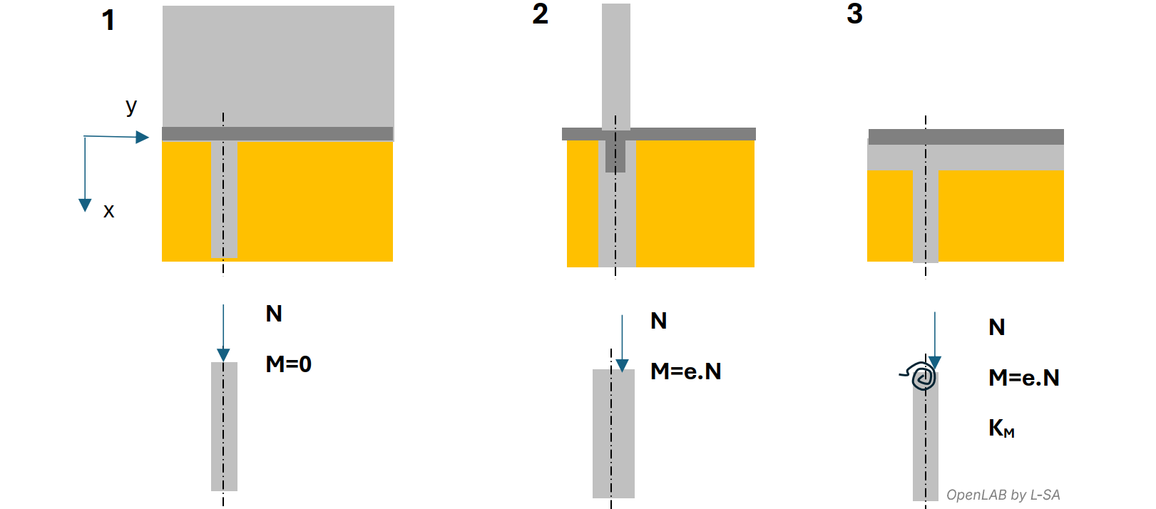
More subtly, Eurocode 2 encourages producing a structural analysis that reflects, as far as possible, the most probable behaviour of the structure. Consistent choices with the relative stiffness of pile/structure help represent the most realistic structural behaviour:
- example 1: if a pile supports a concrete wall‑beam, that beam naturally becomes the component that absorbs the plan‑position deviation of the pile within its plane,
- example 2: if the supported structure has negligible stiffness compared with the pile, then the pile must be specified to absorb possible plan‑position tolerances,
- example 3: if a pile supports a continuous grade beam with flexural stiffness higher than that of the pile, the beam provides partial fixity at the pile head, distributing the deviation effect between the pile and the two spans of the beam based on their relative stiffness.
The load‑transfer document may specify, by category, the boundary conditions to consider for each pile head (pinned, partially fixed, fully fixed), the partial stiffnesses, and the position and inclination deviations to integrate in each direction.
It is also possible to adopt more conservative provisions, easier to describe but inevitably resulting in over‑design — either of the piles or of the supported structure.
In any case, the absence of specification in the contract documents must be a deliberate decision by the design office. In that situation, the structural drawings must reflect a supported structure truly capable of absorbing pile‑position deviations (which is not the case of example 2 above), and the written documents for structural works must clearly restate this to remove ambiguity.
Pile Stiffness vs Structural Stiffness — The B‑P Model
We have just mentioned the possibility of a bending stiffness at the pile head, when the supported structure opposes its rotation in the presence of an applied moment.
Taking this stiffness into account may be interesting or necessary to optimize the design, reduce displacements, or reflect a translational stiffness of the building that is closer to reality (seismic loading).
To implement this behavior, the global structure may systematically incorporate the piles either as beam elements restrained continuously by soil springs, or as matrix elastic supports, as documented for example in AFPS Technical Report No. 38 (2017).
It may also be considered that a bending stiffness at the pile head does not introduce the intrinsic stiffness of the pile, but rather that of the supported structure.
This is the perspective from which we address the topic here.
To do so, we take the example of an elementary building model “B‑P”, composed of a beam “B” restrained by a pile “P”, both elements being assumed to behave in linear elasticity.
The design office B is responsible for the design of B, while the design office P is responsible for the design of P. The two actors interactively perform the modeling of the structure.
We examine three successive configurations of bending stiffness kθ,B of structure B under the effect of a single action, an external horizontal load Hext→B applied to structure B. From a global point of view:
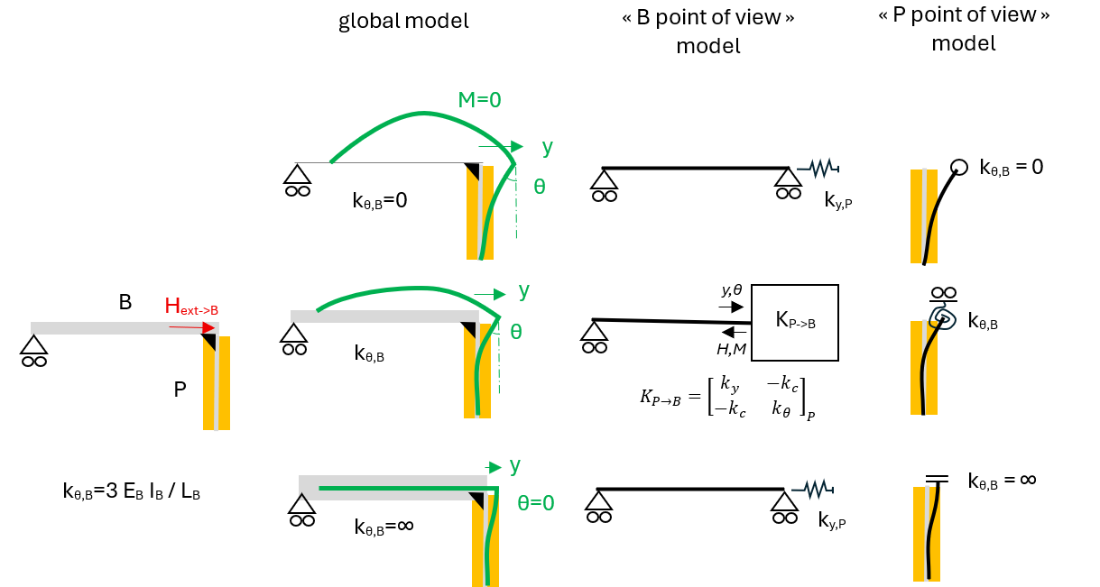
- If kθ,B=0, the pile behaves as if hinged at the head. The head translates by y and also rotates by θ, in a coupled manner. Since the beam has no inertia, the bending moment in the beam is zero, and its deformation follows that imposed by the pile head.
- If kθ,B = 3 EB IB / LB is non‑zero, the beam then opposes the rotation of the pile head due to its inertia, and thus constrains both the displacement y and rotation θ of the pile head. A bending moment M is generated in the beam, which is transferred to the pile head. The pile behaves as partially fixed at the head by kθ,B.
- If kθ,B = ∞, the beam is undeformable and simply translates, imposing zero rotation at the pile head. The pile behaves as perfectly fixed at the head.
In the first and third cases, the coupling between y and θ disappears. From the point of view of B, it is sufficient to specify in the model a horizontal stiffness ky,P to correctly represent P and obtain an accurate structural analysis.
In these two extreme cases, pile P remains the same, but the value of ky,P varies greatly. What affects the value of ky,P is not the intrinsic stiffness of the pile but the stiffness kθ,B of the supported structure B.
For its part, since kθ,B does not depend on the pile, B can determine kθ,B autonomously and communicate it to P.
These observations also apply to the intermediate case “kθ,B arbitrary”.
This intermediate case is more complex to model for B. Indeed, since a horizontal displacement at the pile head necessarily induces a rotation, the model of B must rely not on the usual elastic supports of beam theory, but on a matrix relationship. We discuss this point later.
Let us continue the analysis by reconsidering the three configurations, this time under the effect of a single action, an external bending moment Mext→B applied to B (and not to P).
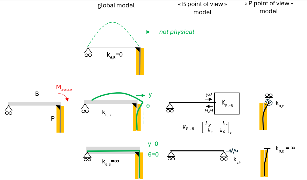
- The case kθ,B = 0 cannot occur. Indeed, if the beam has no inertia, B cannot resist any moment and therefore cannot transmit any moment to the pile head. To convince oneself, one can also examine the equivalent case of an upward point load applied to the span.
- If kθ,B = 3 EB IB / LB is non‑zero, a behavior similar to the previous intermediate case is observed.
- If kθ,B = ∞, the beam being undeformable, it absorbs the entire applied moment without rotating; the pile sees nothing, y = 0, θ = 0.
The previously identified “B‑view” and “P‑view” models are consistent. By linearity, the approach is valid for any pair (H, M) of loadings.
Interactive modeling process between design office B and design office P
Step 1: B independently evaluates the stiffness of the structure kθ,B
- Either kθ,B = 0 if B considers the structure too flexible to absorb a moment at the connection with the pile head
- Or kθ,B = ∞ if B considers the structure “rigid” in the presence of a moment (as in the shear wall example previously discussed)
- Or kθ,B is obtained from a simple calculation based on kθ,B = 3 EB IB / LB, integrating all adjacent beams.
- Or kθ,B is obtained by simulation, modeling the support as a hinge and noting the rotation under an applied unit moment at the node. Then kθ,B = Mapplied / θobtained
- B provides kθ,B to P
Step 2: P incorporates the boundary condition kθ,B at the pile head and determines the stiffnesses kc, ky, and kθ
- If kθ,B = 0 or kθ,B = ∞, P performs a simulation to measure the horizontal displacement under an applied horizontal unit force at the head, and determines ky,P = Happlied / yobtained
- If kθ,B is arbitrary, P performs two simulations, for example:
- [H1, 0] → [y1, θ1]
- [0, M2] → [y2, θ2]
This leads to a system of four equations with four unknowns: ky, kθ, kc1, kc2, enabling the solution of the four unknowns and verifying that kc1 = kc2, denoted kc.
- P provides ky,P, kθ,P, kc,P to B
Step 3: B performs the global structural analysis and obtains the reactions at the pile head
- Either kθ,B = 0 or kθ,B = ∞,
- B provides HB→P to P, and MB→P = 0
- Or kθ,B is arbitrary,
- B provides [HB→P, MB→P] to P, as well as θ.
Step 4: P performs the pile design:
- If kθ,B = 0 or kθ,B = ∞, P applies HB→P at the pile head in the pile model
- If kθ,B is arbitrary, P applies [HB→P, MB→P + kθ,B·θ] at the pile head
In addition to these forces from the global analysis, P also includes the possible effects of inclination and positioning imperfections, if these fall under P’s responsibility.
The term kθ,B·θ corresponds to the portion of moment carried by the supported structure B, which must also be included in the partial fixity at the pile head in P's model. This term must be included to obtain an accurate simulation.
- P provides B with kθ,B·θ: the final moment that the supported structure must absorb on its side.
Step 5: B finalizes the design of the supported structure.
Advantages of the B‑P approach
A more classical approach consists of:
- For design office B: using generalized matrix supports to represent piles in the global model,
- For design office P: modeling the pile alone, assumed hinged at the head and subjected to H, M at the head transmitted by B
This can be represented as follows:
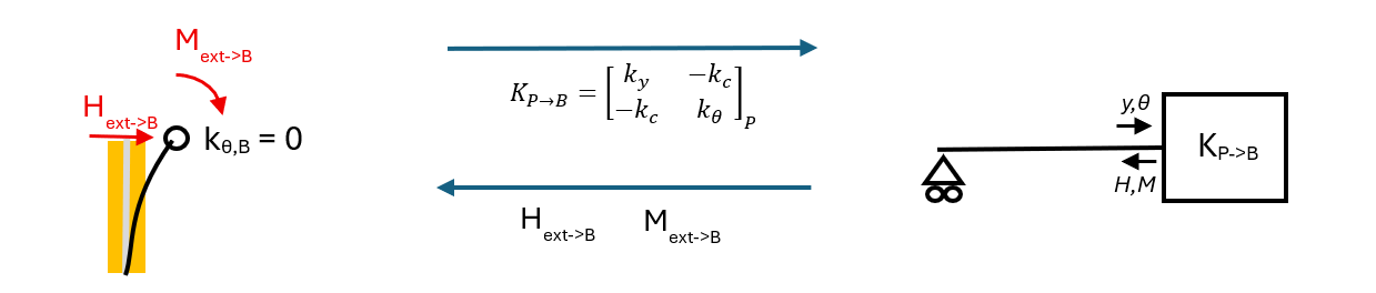
This process appears simpler. However, when examining the previous configurations:
If kθ,B = 0 or kθ,B = ∞,
- The classical approach results in a matrix support in the global model, and an exchange of ky,P, kθ,P, kc,P between B and P.
- The B‑P approach allows a simple horizontal spring ky,P in the global model.
In common practice, when no higher precision is required, the B‑P approach allows simple integration of the most significant bending stiffnesses in the project at each pile location (perfect fixity under shear walls, for example), without complicating the models. It is then sufficient for B and P to agree—documented in the Load Transfer Document—on the restrained directions.
If partial stiffnesses kθ,B must be incorporated, the two approaches have comparable complexity. The B‑P approach simply requires B to provide {kθ,B, θ} to P for pile design. However, in terms of design accuracy, the B‑P approach may be beneficial:
The B model is a macroscopic, linear elastic idealized model, using “average” material behavior laws, with the objective of distributing actions macroscopically among elements and supports.
The P model is a design model that incorporates safety (design behavior laws), the effects of geometric imperfections (e·N2) and inclination (i·N2), potentially non‑linear effects in concrete (cracking, material yielding), soil yielding, and second‑order effects that may amplify the loads.
Under these additional effects, the partial head stiffness kϑ,B provides a significant contribution, strongly influencing bending moments and shear forces along the pile.
Using the B‑P approach enables P to perform a more representative pile design, and allows feedback to B, which can receive its “share” of the design loads derived from the pile design.
Effect on Piles of Column and Wall Inclination Tolerances
The execution tolerances of columns and walls are much smaller than those of piles and less impactful, yet they are worth addressing here.
NF EN 13670 CN §10.4 specifies the applicable tolerances depending on geometry. As a general order of magnitude, they are: 0.5 cm/m in inclination and 1.5 cm in position.
We focus here on the effect of column inclination error, illustrated below:
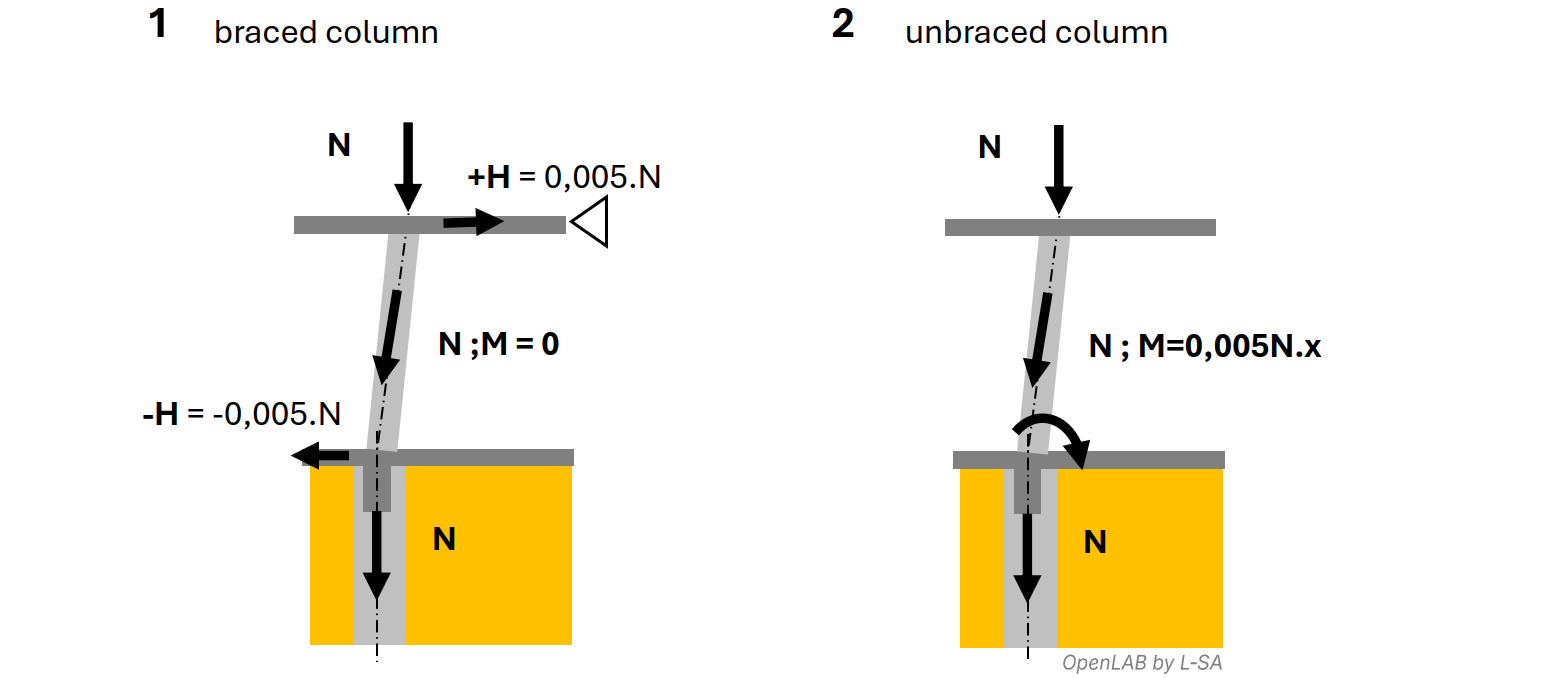
Two cases may occur in practice:
Example 1: Braced Column
In example 1, the column is considered “braced” in the sense of Eurocode 2 — i.e., the upper floor slab is horizontally restrained “downstream” of the studied column, for instance by a shear wall aligned with the direction of loading.
In this case, column inclination generates a horizontal force +H in the upper slab acting as a diaphragm against the wall, re‑aligning the axial force N along the column. An opposite horizontal force –H then appears in the lower slab, transmitting a vertical load back into the pile.
In principle, the pile head should resist –H. However, under the idealised diaphragm action, the +H force from the upper floor is transmitted through the shear wall to the lower floor, where it exactly balances –H.
Although the assumption of infinite diaphragm stiffness is sometimes debatable, horizontal forces induced by braced column inclination are generally negligible.
Example 2: Unbraced Column
In example 2, no shear wall exists downstream. The column itself must provide lateral stability — Eurocode 2 refers to this as an “unbraced column”, or equivalently a “bracing column”.
In this case, column inclination does not generate a horizontal force but induces a bending moment accompanying the axial force down to the pile. At the pile head, the inclination is equivalent to an eccentricity of 0.005·h plus the 1.5 cm position deviation.
For h = 3 m, this yields 3 cm of eccentricity — a non‑negligible value compared with the 10 cm pile eccentricity tolerance, and one that may be amplified by second‑order effects.
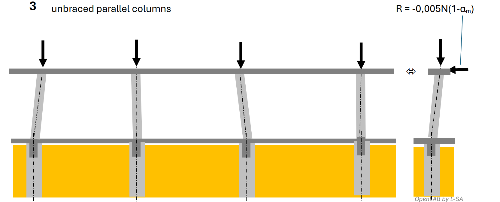
Example 3: Parallel Unbraced Columns
In reality, an unbraced column rarely behaves independently within a structure. Assuming identical inclination direction and sign for every column is rarely representative.
The upper slab diaphragm will in fact relieve the most inclined columns by transferring load to the least inclined ones.
EC2 §5.2(5) allows reducing the inclination considered in design via coefficient αm, which depends on the number m of columns: αm = 0.87 for 2 columns and trends toward 0.7 as m → ∞. An alternative is to keep the full inclination and include a stabilising force R representing diaphragm action (see below).
Effect on Piles… of Pile Inclination Tolerances
The previous discussion on columns helps introduce the effects induced by pile inclination tolerances on the piles themselves.
Unlike columns, the actual inclination of piles after construction is invisible and almost impossible to measure. The only way to account for it is to incorporate possible tolerances directly during design.
Since these tolerances are typically 4 to 6 times larger than those of columns, their effects may be significant, may amplify other imperfections, and may induce second‑order effects.
Moreover, contrary to intuition, a pile whose head is embedded in a supported slab is not automatically laterally braced: in many configurations, piles are the only elements capable of transmitting horizontal forces to the ground.
In the unusual case of a ground‑bearing slab with piles, friction between slab and ground may provide some restraint if dry joints are used — but the total frictional force is rarely sufficient to brace pile heads.
However, we can again consider the diaphragm effect of the supported slab, similarly to unbraced columns, which may reduce the effective pile inclination to be considered in design by up to 30% via αm.
The illustration below shows a building on piles with a non‑symmetric earth pressure. Here, ϑ0 is the pile inclination tolerance specified in contract documents (or norms by default), and ϑi is the reduced inclination used in pile design.
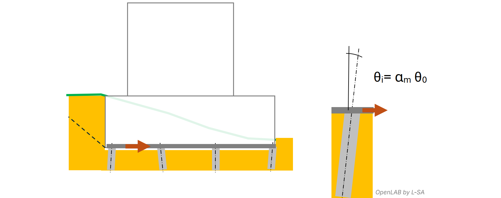
This highlights a limitation of the earlier implicit interface rules between structural works and special foundations:
If the structural design office does not include in the ULS load‑transfer document the horizontal force induced by pile inclination, i.e. H = αm · ϑ0 · N, then the special‑foundations engineer will assume that it is the structural‑works package that must resist these effects.
Yet this assumption is often unrealistic depending on building configuration, since horizontal forces may only be transferrable to the ground through the piles.
Summary in the Form of an Example
We propose here a synthesis of the aspects discussed above, through an example of a ground‑floor slab supported by a network of grade beams and piles, analysed using two different strategies.
The example and its treatments under the two strategies are intentionally simplified.
Strategy 1
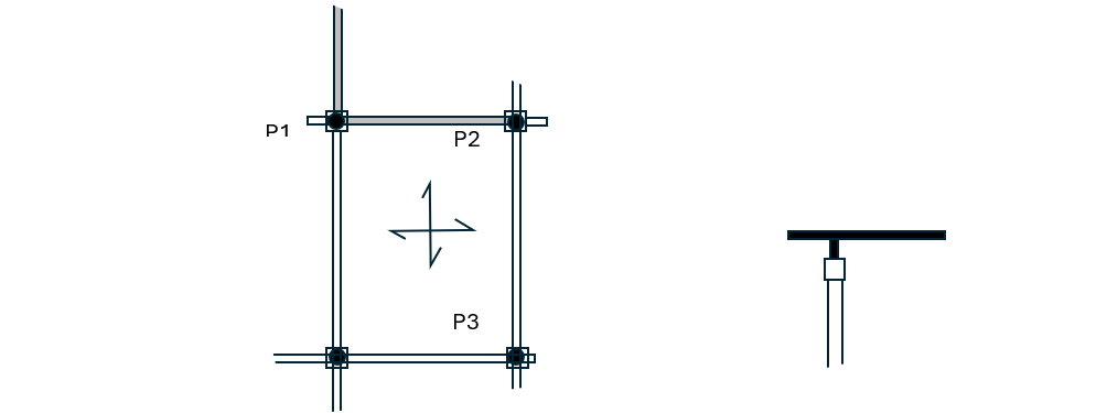
The pile heads are modelled as pinned. Their dimensions, connections, and reinforcement with the supported structure are not intended to provide moment fixity.
The effects of pile plan‑position deviations fall under the responsibility of the supported structure, corresponding to the default interface rules when no explicit information is provided. However, the design office explicitly restates this in the written documents, as well as the underlying assumptions, to avoid ambiguity.
In this strategy, a bidirectional network of grade beams makes the assumption feasible: the beams can resist the effects of pile plan‑position deviations, in all directions and senses, within tolerances.
Concerning inclination tolerances, the design office departs from “implicit rules” by explicitly stating that piles must be designed to resist forces induced by inclination errors, as the opposite assumption is considered unrealistic for this project.
Load‑transfer document provided by the Structural Engineer to the Special‑Foundations Engineer and annexed to both trade packages
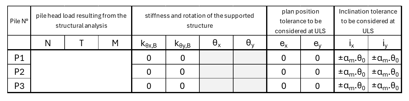
Specifications included in both Structural‑Works and Special‑Foundations written documents
The forces induced by pile plan‑position deviations, within tolerance limits, are included in the design of the supported structure (structural‑works package), in all possible directions and senses of deviation.
The forces induced by pile inclination deviations, within tolerance limits, are included in the pile design (special‑foundations package), in all possible directions and senses of deviation.
The execution tolerances considered at tender stage are ϑ0 = 2 cm/m in inclination and e0 = 10 cm in plan position, with piles assumed to be installed after excavation (low platform).
Any change to these assumptions must be explicitly specified in the offer.
Strategy 2
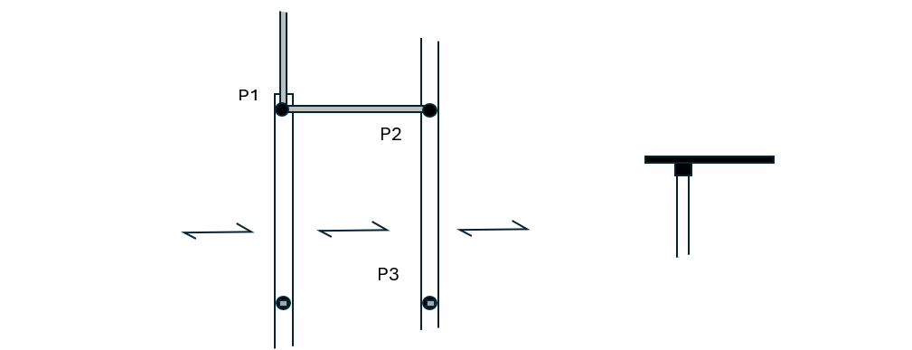
The slab is supported on two sides by grade beams which also act as pile caps. The grade beams, wall‑beams, and piles have defined stiffnesses used both in the global structural model and in the pile structural model.
The load‑transfer document directly states the stiffness assumptions at each pile head as well as the imperfections to include in pile calculations. These assumptions are reflected in both trade packages.
Load‑transfer document provided by the Structural Engineer to the Special‑Foundations Engineer and annexed to both trade packages
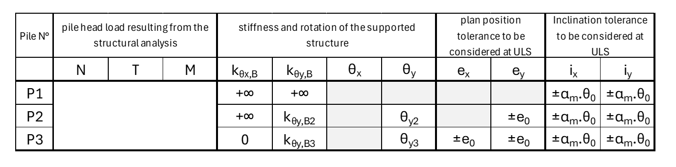
Specifications included in both Structural‑Works and Special‑Foundations written documents
The forces induced by pile plan‑position deviations, within tolerance limits, are integrated:
- either into the pile design (special‑foundations package),
- or into the supported‑structure design (structural‑works package),
- or partially in both trades, depending on intermediate stiffness conditions.
The annexed load‑transfer document describes, case by case, the assumptions to be used by each trade.
The forces induced by pile inclination deviations, within tolerance limits, are included in the pile design (special‑foundations package).
The execution tolerances considered at tender stage are ϑ0 = 2 cm/m in inclination and e0 = 10 cm in plan position, with piles assumed to be installed after excavation (low platform).
Any change to these assumptions must be explicitly specified in the offer.
Finally, the rotational stiffnesses of the supported structure and the rotations obtained from global analysis are included in the load‑transfer document.
Conclusion of This Article
The execution tolerances of piles, inclination and position deviations, and working platform elevations are not mere details: they directly influence the geometry of a structure, the design logic, the structural sizing, and the allocation of responsibilities between Structural Works and Special Foundations.
A load‑transfer document (DDC) is therefore not a simple exported spreadsheet of forces, but a true design document that defines the geometric and mechanical assumptions on which the entire interface between the two trades is built. Advantageously, the DDC may also make explicit the bending‑stiffness assumptions between the structure and each pile.
By clearly stating the tolerances considered, the boundary conditions at pile heads, the associated effects (eccentricities, relative stiffness), and the chosen assignment of responsibilities, the structural engineer secures the project, prevents interpretation inconsistencies, and ensures that each contractor works within a clear and controlled framework.
Conversely, lack of clarification may lead to an implicit distribution of effects that is less appropriate. In a context where contractor variants, proprietary methods, and techno‑economic optimisations are common practice, the quality of the DDC becomes a key factor in preserving the structural coherence, contractual balance, and overall robustness of the project.