
 FR
FR 
Elastic structural analysis, limited redistribution, and plastic analysis. Study on an example, verification of ductility, and the limits of these models
This article presents the four structural analysis methods proposed by Eurocode 2 for continuous beams, and shows how simplified approaches (elastic, limited redistribution, plastic) deliberately bypass the pursuit of the exact solution.
It explains the mechanisms of hinge formation, the conditions for valid redistribution, the verification of plastic rotation capacity, and the biases of linear models when cracking and stiffness loss become predominant.
Finally, it highlights possible discrepancies between simplified analysis and actual behaviour, especially regarding deflection, second‑order effects, and redistribution at SLS.
This topic is the final part of our series dedicated to the flexural behaviour of reinforced concrete beams (4/4).
- The three simplified methods of Eurocode 2
- Considering plastified beam segments in ULS structural analysis
- ULS structural analysis of a two‑span slab
- Explicit verification of rotation capacity according to EC2 §5.6.3
- The plastification of the support zone using exact analysis
- Dissonances in Eurocode 2 regarding deformation compatibility
Back to the previous article: Hyperstatic Structures : the Unique Deformation‑Compatible Solution
The three simplified methods of Eurocode 2
For continuous beams, which are the most common hyperstatic systems designed in building structures, Eurocode 2 identifies four structural analysis methods:
- Linear elastic analysis (§5.4)
- Linear elastic analysis with limited redistribution of moments (§5.5)
- Plastic analysis (§5.6)
- Nonlinear analysis (§5.7)
The last method, nonlinear analysis, corresponds to the general case presented in the previous article. It is scarcely detailed in Eurocode 2 and rarely used in practice, because it is complex to implement and computationally demanding.
It incorporates material nonlinearity, the necessity of deformation compatibility, and its inherently general applicability at SLS, ULS, first and second order — unlike the three other methods.

As mentioned in the first article of the series, Eurocode 2 provides three much simpler methods, which are linear approximate methods that deliberately bypass the search for the exact solution and aim to make design practically accessible by removing the need for iterative calculations.
Eurocode 2 therefore allows the use of:
- A linear elastic structural analysis, assuming that sections are elastic, linear, uncracked and without reinforcement. Eurocode 2 does not require any verification of deformation compatibility, regardless of reinforcement layout, cracking, or steel plastification in critical sections.
- A plastic analysis, in which plastic hinges are positioned at specific locations along an elastic beam, each hinge resisting a given ultimate moment regardless of rotation. Each hinge removes one degree of hyperstaticity and replaces continuity equations with imposed moments on adjacent spans.
Hinges may be positioned as long as the resulting spans remain isostatic. These spans are individually modelled as linear, elastic, uncracked and unreinforced.
- An analysis with limited redistribution, which is a special case of plastic analysis where plastic hinges are placed at some or all intermediate supports.
Considering plastified beam segments in ULS structural analysis
Regarding the behaviour laws of reinforced concrete sections, EC2 simplified methods essentially replace the nonlinear moment–curvature relationships with straight lines, as shown below:
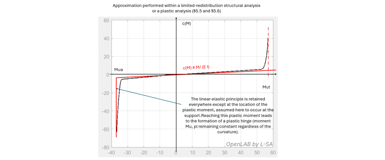
As shown in the graph, linear elastic analysis completely hides any redistribution effects that may occur due to the significant stiffness loss near ultimate moments: all nonlinear effects effectively disappear in favour of an infinite elastic behaviour.
However, in ULS analysis, plastic zones can form in the most highly loaded regions or in deliberately under‑reinforced zones.
These zones, where the steel has entered its plastic plateau, may extend across a width of one to two section depths. The stiffness may drop by a factor of 10 in beams and even 100 in slabs, causing large rotation jumps that elastic models cannot explain.
To correct this bias and include the phenomenon in simplified form, Eurocode 2 introduces the plastic hinge, illustrated below as an idealised plastic plateau completing the elastic curve near ultimate moment:
In structural analysis, a plastic hinge is introduced as a point rotation discontinuity, releasing one degree of hyperstaticity and replacing it with an imposed moment Mua on each side.
The introduction of a plastic hinge requires, in a second step, verification that the rotation difference between the two sides of the plastified segment is physically accommodated by the reinforced concrete section — a verification known as rotation capacity or deformation compatibility. Alternative formulations such as : hinge opening capacity, section curvature capacity, or rotation capacity of the plastic segment can be helpful for improving understanding.
EC2 limits the neutral‑axis depth to ensure that section equilibrium occurs with significant yielding of tension steel.
ULS structural analysis of a two‑span slab
The three simplified structural analysis methods, stripped of the iterations required for the exact solution, allow following the EC2 sequential design process: step 1: structural analysis → step 2: cross‑section design → step 3: SLS checks for hyperstatic beams, as for isostatic beams.
This chapter illustrates the process on an example: a two‑span slab.
Elastic beams connected by plastic hinges
The slab has hyperstatic degree 1. We consider ULS plastic analysis by placing a plastic hinge at the intermediate support, reducing the model to two isostatic slabs subject to transverse loading and an imposed moment at one support.
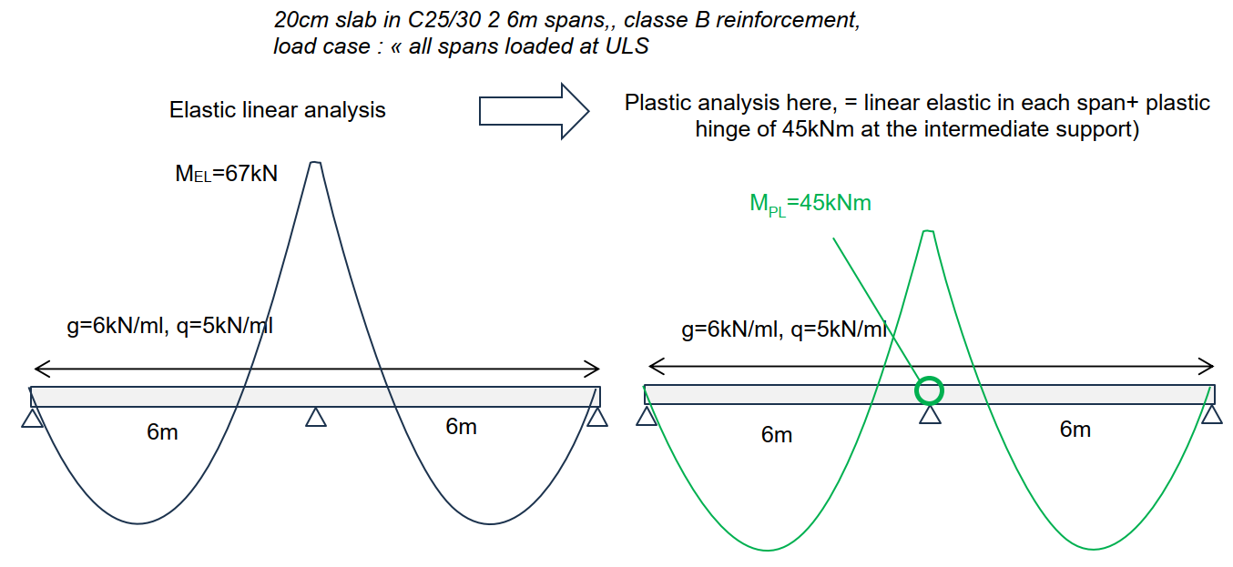
- As previously discussed, the engineer first constructs a linear elastic model of the beam (uncracked, unreinforced).
- Under the ULS load case “all spans loaded”, the maximum support moment is calculated as 67 kNm (assuming a monolithic 20 cm‑wide support).
As in classical two‑span beam theory, the support moment is much higher than the span moment (67 kNm vs 39 kNm).
This value is a bias of linear elastic analysis, which assumes infinite elasticity: c(M) = M/EI for any moment amplitude.
In reality, at ULS, the moment peak causes the support regions to enter the plastic domain, resulting in a large stiffness drop. This inevitably leads to moment redistribution towards the spans. The slab will never actually reach 67 kNm, even if designed to resist it.
To better reflect physical behaviour and optimise reinforcement, the engineer corrects the elastic analysis by placing a plastic hinge at the intermediate support, reducing the support moment and compressing the ULS envelope.
The hinge moment is set at 45 kNm, a 30% reduction.
Then the ULS envelope is built. For each successive load arrangement, the linear elastic model is used first (without hinge). A decision is made for each case:
- if the elastic support moment is < 45 kNm, the hinge does not activate, and the moment curve is not redistributed
- if the elastic support moment is > 45 kNm, the hinge activates, and the moment curve is redistributed with a cap at 45 kNm
This yields the following ULS envelope:
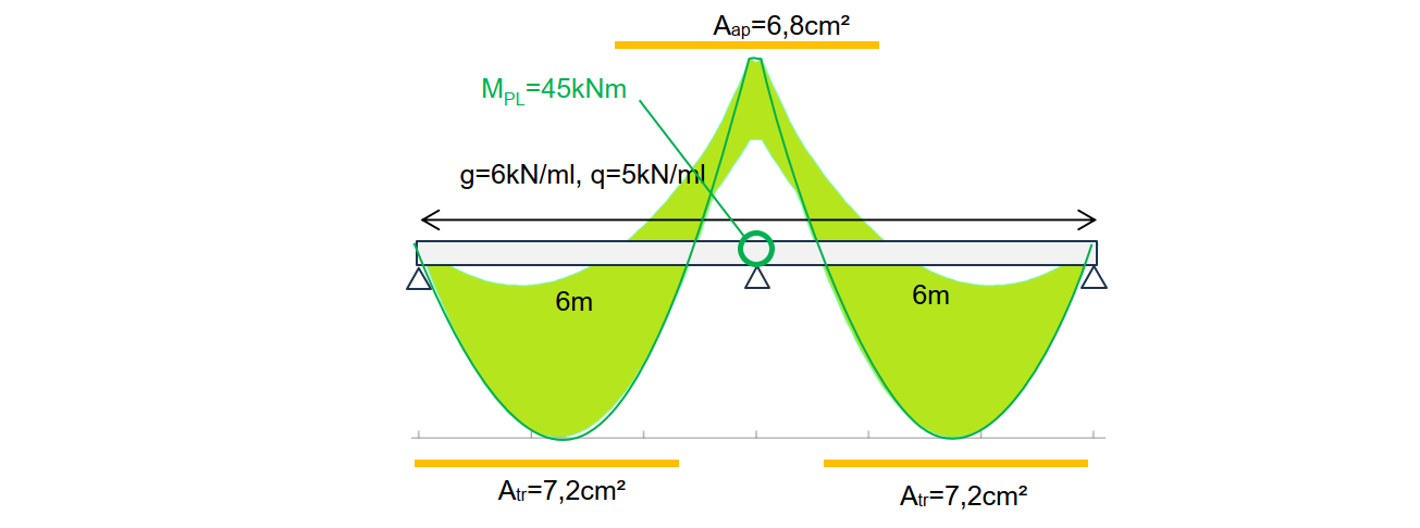
NB: introducing the plastic hinge produces a 46% reduction of steel at the support and a 6% reduction in span steel. This strategy is very efficient in terms of reinforcement consumption.
Simple verification of the plastic hinge opening capacity
In structural analysis, we assumed a plastic hinge limiting support moment to 45 kNm, creating a rotation discontinuity on each side of the plastified slab segment.
To validate this ULS design, we must check that the chosen reinforced concrete section at the plastified zone can indeed withstand this rotation discontinuity while still resisting 45 kNm, as required by EC2 §5.6.1(2)P.
We have three options to validate the approach:
- The plastic analysis with a hinge at the support is a limited redistribution analysis, so we may apply criterion 5.10a.
Here, δ = MPL/MEL = 0.7. After redistribution, μ = 0.106, xu/d = 0.14, k1 = 0.44, k2 = 1.25, k5 = 0.7. Thus δ ≤ max(0.61, 0.7) = 0.7 → OK.
- We may also apply §5.6.2(2): xu/d is sufficiently small, reinforcement is class B, and the moment ratio is close to 1 → OK.
- Finally, we may explicitly verify the plastic rotation and compare it with limits in §5.6.3.
Explicit verification of rotation capacity according to EC2 §5.6.3
The plastic hinge has therefore removed the hyperstaticity of order 1.
For each load case, we analyse:
- the first span, now an isostatic elastic slab on two supports, loaded by a line load and a support moment on the right → its right support rotation is ϑg
- the second span, analysed similarly → its left support rotation is ϑd
The rotation discontinuity at the plastic hinge is: δϑ = ϑd − ϑg.
EC2 follows a sequential process: deformations are evaluated in step 1: structural analysis using mean behaviour laws, not design laws.
Therefore, even at ULS, we must evaluate the most probable rotation, using mean laws — as specified in §5.6.3(3).
Ideally, we would include in the calculation of ϑg and ϑd:
- tension‑stiffening effects
- progressive cracking
- plastification
However, §5.6.3 implicitly fits into the context of §5.5–5.6 analyses, assuming beams are linear and elastic between plastic hinges. EC2 is not explicit, but tables 5.6(N) were likely derived with this assumption.
Thus, when applying §5.6.3, we should:
- ignore reinforcement
- ignore cracking
- assume linear elasticity with modulus Ecm
Suppose the hinge rotation discontinuity is δϑ = 20 mrad. Then, applying §5.6.3:
- distance from max moment (x = 6.1 m) to zero moment (x = 7.1 m) = 1 m → λ = 1/0.16 = 6.25 → kλ = 1.44
- figure 5.6N gives θpl,d = 14 mrad for xu/d = 0.14
- correcting with kλ: θpl,d ≥ 20 mrad → OK
Approach According to the Future EC2
The future EC2 revises the approach to this topic: in the evaluation of ϑg and ϑd, it requires taking into account cracking in adjacent spans, which is closer to the fundamentals of EC2. Diagram 5.6(N), which indicates the allowable rotations, is replaced by an explicit formula (7.18), from which it becomes clearer that the calibration was made using this assumption. It should also be noted that the future EC2, in linear elastic analysis at ULS, in §7.3.1(3), proposes to account for reduced stiffnesses if cracking is “expected” in the loading situations considered.
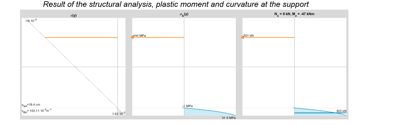
The plastification of the support zone using exact analysis
A general‑purpose numerical tool (MGI) can determine the exact nonlinear solution for a given reinforcement layout. Unlike plastic analysis, nonlinearity is evaluated continuously along the beam. Near the intermediate support, the results may be illustrated as:
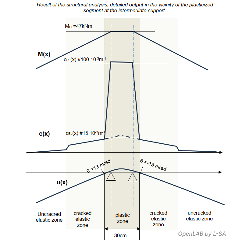
The graph shows:
- plastic moment = 47 kNm
- steel plastification (plastic hinge) extends across 30 cm (1.5h)
- total rotation across plastified zone = 30 mrad
- this rotation consists of:
- elastic rotation: 4.5 mrad (= 15×10⁻³ × 0.30)
- plastic rotation: 25.5 mrad (= 85×10⁻³ × 0.30)
Dissonances in Eurocode 2 regarding deformation compatibility
Some use‑cases reveal the limitations inherent in bypassing the exact solution, using the simplified assumptions of §5.4 to §5.6, or the application of the process : Step 1 – structural analysis, Step 2 – section design.
Deflection of continuous beams
Using one of the three simplified analysis methods and/or an explicit (non‑iterative) sequential process does not allow rigorous deflection calculation for a continuous beam.
Suppose internal forces {N, T, M} were determined using a simplified elastic analysis (§5.4). Computing cracked inertias along the span and then performing double integration of curvature only yields a rigorous deflection for an isostatic beam.
For a continuous beam, the computed shape f(x) likely does not sit on both supports: deformation compatibility at the intermediate support strongly affects moment distribution and adjacent spans. Lack of iteration compromises rotation compatibility.
Section Design Following a Nonlinear Structural Analysis
A nonlinear structural analysis determines the “exact” solution, meaning the response that is fully consistent, at every section of the continuous beam, with the material behaviour laws for concrete and steel as defined in EC2: contribution of tension‑stiffening, progressive cracking, concrete and steel yielding, etc.
In a case such as the previous two‑span slab example, this structural analysis dictates the exact redistributed moment at the support section at ULS: 47 kNm, depending on the reinforcement layout and the material properties.
If we now try to place ourselves back into the Eurocode 2 framework:
- Step 1: structural analysis
- Step 2: section design
We have completed Step 1 and move on to Step 2 to verify the resistance of the support section under this moment of 47 kNm.
However, according to EC2, the material behaviour laws used in the “design” step are more unfavourable than those used in the “structural analysis” step. We therefore find that the proposed section only resists an ultimate moment of 45 kNm and does not satisfy the requirement for 47 kNm.
We would then have to increase the top reinforcement over the support so that the section resists 47 kNm, and then rerun the structural analysis with this new reinforcement layout, with the process repeating endlessly, each iteration reducing the amount of moment redistribution at the support…
Two solutions are possible to make this design process convergent:
- Accept a permissible “over‑stress” at ULS for reinforced concrete sections whose moment has been redistributed
- Adopt a single material law applicable to both Step 1 and Step 2, effectively merging the steps
The first solution appears most appropriate for continuous beams, in order to remain aligned with current design practice.
The second solution appears more suitable for columns analysed with second‑order effects, and this is already what Eurocode 2 proposes, as explained in the following section.
Column design under the general method
The general method for column design requires compatibility of flexural deformations and therefore cannot follow the classical EC2 sequence “step 1 structural analysis → step 2 section design”.
EC2 therefore explicitly merges step 1 and step 2, allowing iteration and requiring a single behaviour law σ = Ecd ε for both analysis and design.
Redistribution of moments “at engineer’s discretion”
Once reinforcement distribution is defined in a continuous beam, the moment distribution is not chosen by the engineer but imposed by deformation compatibility, at both ULS and SLS.
Redistribution arises:
- primarily through steel plastification and hinge formation → only at ULS
- marginally through cracking, in slabs when cracking occurs at the support but not simultaneously in span → sometimes at SLS
All EC2 redistribution criteria are based on plastic capacity at ULS via limits on xu/d.
Without iterative analysis, these criteria ensure a coherent match between simplified ULS analysis and section design.
However, accepting the same redistribution at SLS as at ULS is questionable, since SLS sections cannot plastify.
In slabs, cracking may sometimes produce small SLS redistributions, but this is limited compared to ULS plastification effects.
In beams, cracking occurs very early, and the ratio of cracked-to-uncracked inertia is small. Redistribution at SLS is therefore often impossible to demonstrate.
Exact SLS analysis of a beam, including progressive cracking, often shows no redistribution at the support, leading to excess stresses in bottom concrete, tensile steel and crack widths at the top fibre.
This series dedicated to the study of the flexural behaviour of reinforced concrete beams and one‑way slabs concludes with several open points for discussion. Feel free to comment, enrich or correct these articles using the discussion sections available at the bottom of the page (OpenLAB users). Thank you, and see you soon.