
 FR
FR 
The material laws in EC2 vary between structural analysis and cross‑section design, incorporating different levels of physical complexity in the behaviour of concrete and steel depending on the objectives pursued.
This article details the different behaviour laws for concrete and steel, their distinct uses (structural analysis vs cross‑section design), and their limitations.
It explores how phenomena such as plastification, cracking, or even the tensile resistance of concrete are taken into account, and clarifies the safety factors and the possibilities for linearisation or other simplifications authorised by EC2 depending on the design step.
This topic is the second part of a series devoted to the flexural behaviour of reinforced concrete beams (2/4).
- Concrete behaviour laws in compression
Back to the previous article: Understanding Eurocode 2: terminology, calculation framework, and analysis–design logic.
Concrete behaviour laws in compression
Below is a representation of the change in the assumed behaviour law of concrete between step 1 (structural analysis, in blue) and step 2 (cross‑section design, in red), for a standard C25/30 concrete.
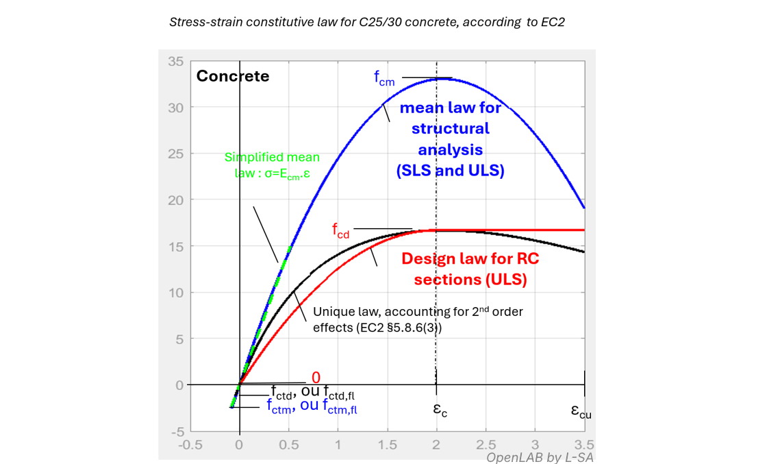
The choice of colours and annotations in this graph aims to facilitate the understanding of the domain of use of each law, according to the logic of Eurocode 2. The following paragraphs comment and progressively clarify the various key aspects of this graph.
“Mean resistance” VS “design resistance” for concrete in compression
We observe a huge difference in the values to be used for concrete behaviour between the two approaches. This difference results from the combination of an offset of 8 MPa between fcm and fck, and a partial safety factor γc = 1.5 between fck and fcd. This safety margin reflects the large statistical variability between the intended strength at design stage and the actual measurable strength of concrete, depending on construction conditions. It also accounts for the variability in geometry between the intended formwork and reinforcement layout and the geometry actually achieved on site.
NB: Annex A of Eurocode 2 allows improving concrete design values by 15% and steel values by 10% when geometry and concrete strength variability are particularly well controlled.
Since the purpose of the “design law” is not to most accurately represent the real stress–strain relationship—unlike the mean law—but rather to incorporate safety, the curve shape can be simplified into a “flat plateau” complemented by a safety factor ensuring, on average, the partial factor γc.
Limitations of the parabola‑rectangle law
For structural analysis, Eurocode 2 theoretically admits only one behaviour law for concrete: the “mean law” shown in blue in the graph above (§3.1.5). This law is essential when compatibility of axial or flexural deformations must be established.
In other cases, and to meet everyday design needs, §5.4 allows major simplifications, up to linearisation and symmetric behaviour for both SLS structural analysis and ULS structural analysis.
For cross‑section design, the mean law is reduced by safety factors to obtain the design law (black curve below). For practical RC cross‑section design, this design law is itself approximated by two simplified models: the bilinear law (not shown) and the parabola‑rectangle law (red curve). This parabola‑rectangle law is then further simplified by a rectangular stress block (pivot B). The sequence of simplifications is illustrated below.
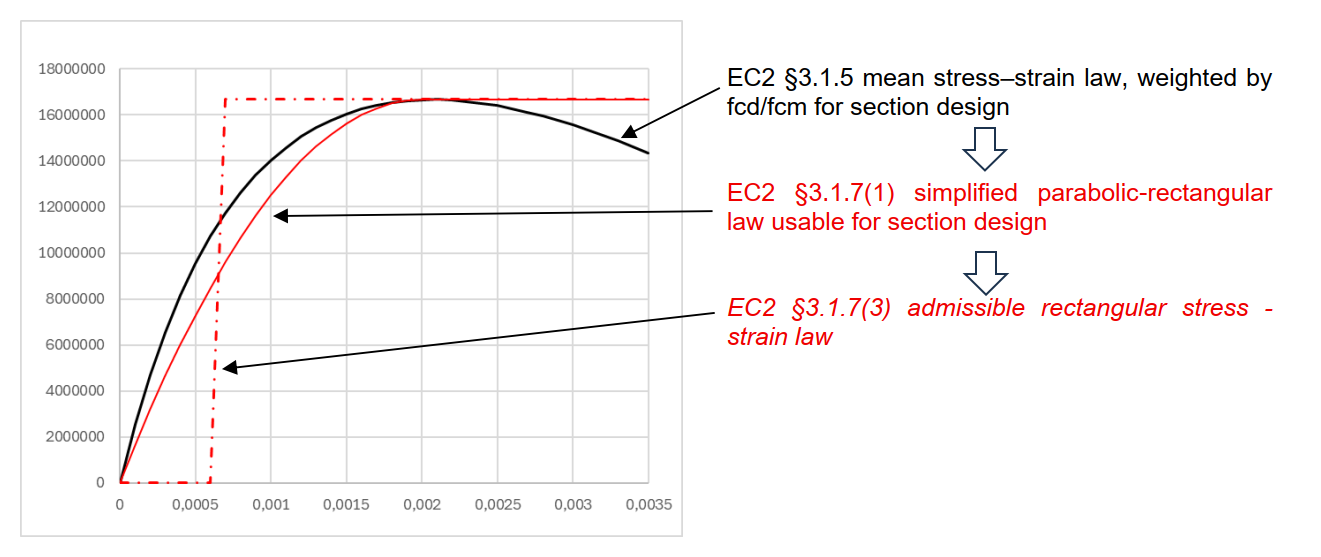
Simplified behaviour laws for cross‑section design
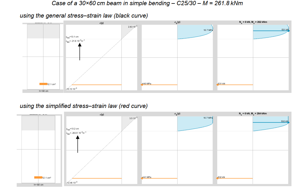
These “red” design laws are much easier to handle than the full law while still providing reasonably accurate estimates (within 2–3%) for lever arms and reinforcement design at ULS.
However, these laws overestimate curvature by 20 to 30% compared to the black curve, making them totally unsuitable for deformation calculations in general, and for plastic hinge calculations in particular.
A single law for concrete in compression when second‑order effects are present
When second‑order effects are present, deformation compatibility must be enforced, which makes the sequential “step 1 → step 2” procedure impossible. A single iterative calculation is required, using a behaviour law that provides both design safety and a realistic deformation prediction. For this reason, the blue and red curves are discarded in favour of the black curve.
These notions are developed further in a later section.
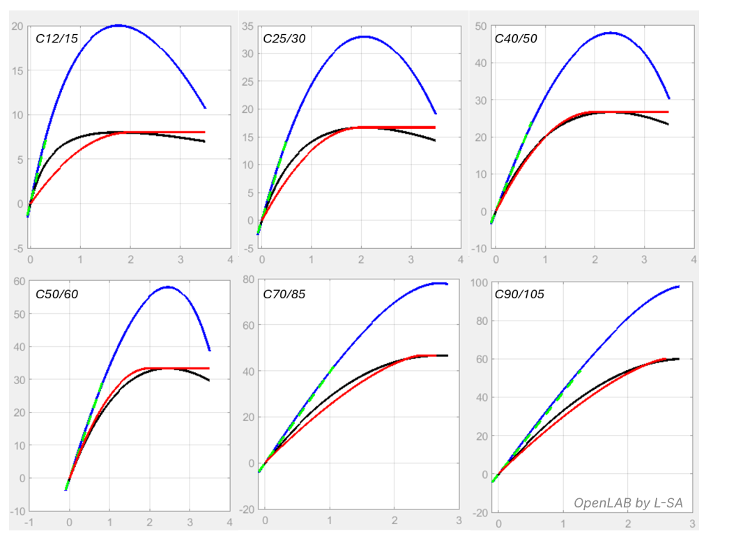
Significant evolution of the curves from C12/15 to C90/105
The figure below shows the evolution of both mean laws and design laws as a function of concrete strength class. The shape of the curves varies greatly with concrete characteristic strength.
Above 50 MPa, the ductility of concrete decreases, and the design law introduces a safety reduction on the ultimate strain limit (εcu2 < εcu1).
Creep effect
Concrete is a material that creeps: under a permanently applied compressive stress, the material continues to “shorten” over time through a progressive and irreversible phenomenon until long‑term stabilization is reached.
Eurocode 2 describes this concept in §3.1.4 through the concrete creep coefficient noted φ(t,t0).
The phenomenon may be introduced into the constitutive law by means of a deformation multiplier: σc = f((1 + φ(t,t0)) ε), which, when the law is linear elastic, is equivalent to adopting a Young’s modulus Ecm / (1 + φ(t,t0)).
Eurocode 2 provides different approaches for determining the creep value over time and at infinite time, but these rely on parameters such as ambient humidity, cement type, or loading age, which the design engineer does not always know at the design stage.
In the absence of a more refined calculation, one often assumes φ∞ = 2, and then derives the effective creep coefficient φef to be considered in the analysis depending on the proportion of long‑term effects.
A practical relationship
It is often necessary to switch between the creep coefficient φ, the ratio between long‑term and instantaneous modulus, or the share of long‑term effects in a given load case.
For this purpose, it is useful to name these ratios, for instance:
- τφ: long‑term effect ratio τφ = “Ed SLS,QP” / “Ed”
- ηef: effective reduction coefficient of the modulus ηef = Eef / Ei
- η∞: modulus reduction coefficient at infinite time η∞ = E∞ / Ei
Additionally:
- φef: effective creep coefficient (EC2 §5.8.4(2)) φef = τφ · φ∞
- φ∞: creep coefficient at infinite time
The following relationship can therefore be established:

This formula makes it possible to determine the effective modulus of the material to be used in a given calculation, based on the instantaneous modulus and on the limit state considered.
This formula may be used for concrete but also in geotechnical engineering, where soil creep is handled through “long‑term” versus “short‑term” stiffness.
Creep in ULS according to the Eurocodes
This paragraph discusses the case of soil in parallel with that of concrete.
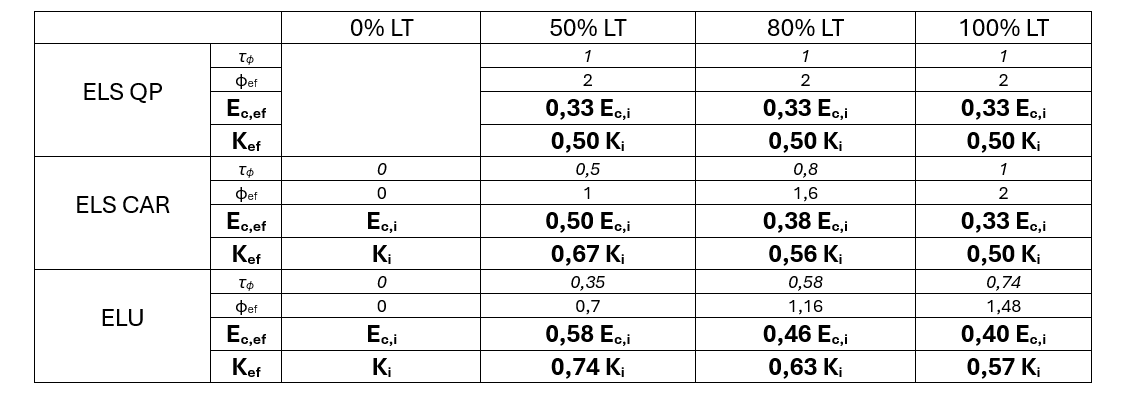
Let us assume a model where loads are purely permanent (Q = 0), and where Ec,∞ = 1/3 Ecm for concrete and K∞ = 1/2 Ki for soil, which are common values. The previously established formula allows us to determine the effective values to be used:
- SLS τφ = 1/1
- for concrete: η∞ = 0.33 → ηef = 0.33 → Ec,ef = 0.33 Eci
- for soil: η∞ = 0.5 → ηef = 0.5 → Kef = 0.5 Ki
- ULS τφ = 1/1.35 = 0.74
- for concrete: η∞ = 0.33 → ηef = 0.33 → Ec,ef = 0.40 Eci
- for soil: η∞ = 0.5 → ηef = 0.5 → Kef = 0.57 Ki
The values obtained at SLS are those expected, whereas those obtained at ULS are noteworthy: indeed, E∞ and K∞ are not used in ULS calculations, even when 100% of the loads are long‑term.
In a way, Eurocode considers that the “0.35G” increment added to G in ULS combinations provides a “safety margin” for the ultimate calculation, making it unnecessary to reinforce the calculation further by explicitly accounting for creep.
The table below provides a more general summary of the values of Ec,ef and Kef, depending on the proportion of short‑term (ST) and long‑term (LT) effects, assuming Ec,∞/Ec,i = 1/3 and Kv/Ki = 1/2.
Strictly speaking, when modelling uses a modulus Ec applied to cracked or homogenized inertias, the effect of creep is smaller than that estimated for concrete alone, since steel does not creep.
Considering concrete in tension
Tensile strength of concrete
The tensile strength of concrete is low and highly dispersed statistically, as shown in Table 3.1 of EC2, with values varying by a factor of two. In principle:
- fctm is the mean value of tensile strength, to be used by default for structural analysis, while
- fctd, based on the 5% lower fractile, is the safety‑based tensile strength to be used in ULS section design when the text allows it.
fctm and fctd correspond to tensile resistance under direct tension. Eurocode 2 states that tensile resistance in bending can be significantly higher than direct tensile resistance and depends on section depth. Article 3.1.8 therefore introduces fctm,fl, which may be used per Article 7.4.3 for beams in bending or bending with compression.NOTE
The table below summarises the conditions for considering the tensile resistance of concrete depending on the calculation step and system configuration, notably for an “ideal” model based on EC2 principles (later sections address the simplifications permitted for structural analysis):
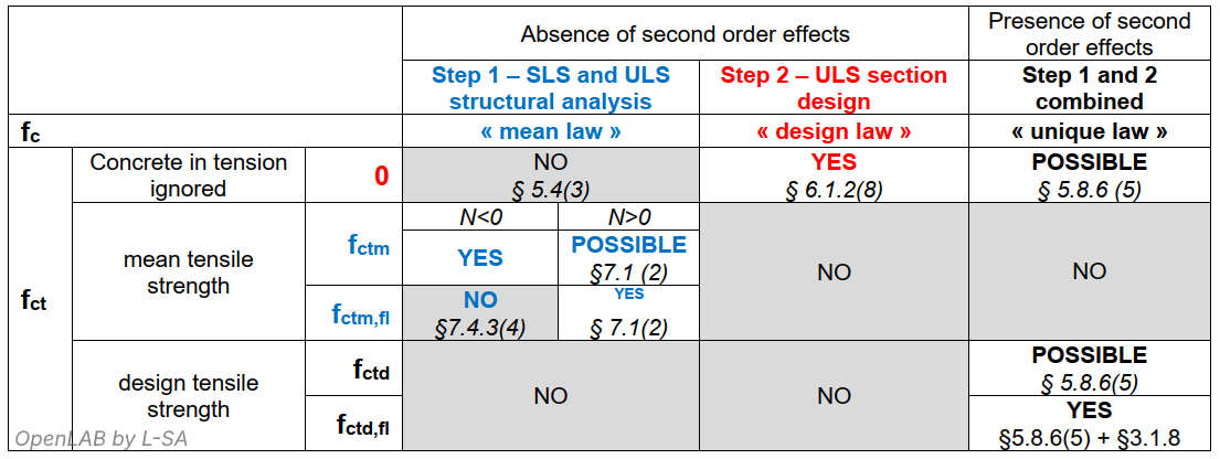
The table shows the appearance of fctd,fl as introduced in §3.1.8.
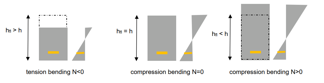
NOTE: §7.4.3(4) states that in axial tension (N < 0), fctm must be used rather than fctm,fl. This rule distinguishes between “direct tension” and “bending tension” when choosing the appropriate tensile strength. However, an alternative approach for combined bending could be to retain formula 3.23 but replace h by a fictitious depth “hfl”, as shown below, ensuring continuity in the use of fctm,fl. In the example, the lower zone of the beam behaves similarly in the three cases; thus, identical tensile limits could reasonably be adopted. The same applies for deciding between fctd,fl and fctd.
Integrating the ζ‑factor: progressive cracking
In its aim to determine the most probable values of internal forces, stresses, strains and displacements, structural analysis includes the contribution of the most probable tensile strength of concrete, i.e. fctm or fctm,fl, just as it uses the “mean law” in compression.
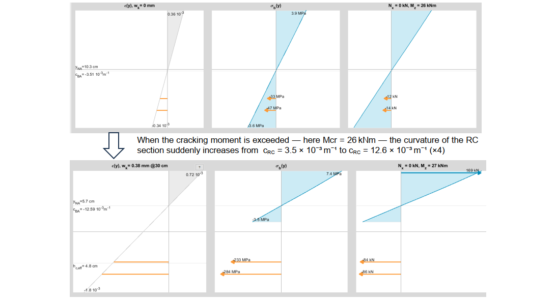
The stress–strain relationships allow determining the curvature as a function of bending moment. There is a major discontinuity near cracking. The figure below illustrates the increase in curvature (here ×4) at the moment the critical cracking moment is exceeded:
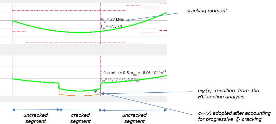
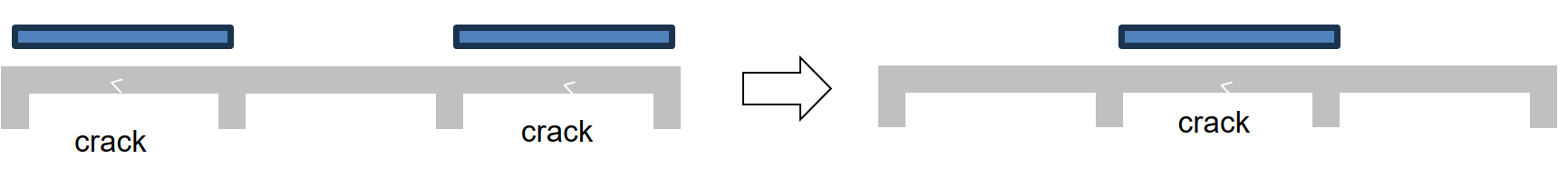
On a more macroscopic level, not all sections crack simultaneously along the beam as soon as the cracking moment is reached. When two successive sections crack, the span between them remains uncracked at first. Cracking is therefore progressive. This is not visible when analysing a single section, but it plays a major role in calculating the beam deformation.

To transition from the section curvature cBA to the mean curvature d²u/dx² used to determine deflection, EC2 introduces a coefficient ζ accounting for progressive cracking (7.4.3).
The curvature used for numerical integration lies between the uncracked curvature (aI) and the cracked curvature (aII). ζ tends toward 1 as bending moment approaches the ultimate value.
![]()
In the example above, at first cracking, EC2 assigns ζ = ½, so the mean curvature is: cint = d²u/dx² = ½ (3.5×10⁻³ + 12.6×10⁻³) = 8×10⁻³ m⁻¹.
The magnitudes involved demonstrate the importance of including not only concrete tensile resistance but also progressive cracking in structural analysis, as required in 7.1(2).
Considering flanges in tension over supports
In the chapter on “structural modelling”, EC2 §5.3.2.1 provides rules for limiting the width of the effective compression flange in T‑beams in span, uniformly for all limit states.
The text is silent regarding the treatment of flanges in tension, which deserves clarification in light of EC2 principles discussed earlier.
In step 2 (ULS cross‑section design), the contribution of concrete in tension is ignored for safety. Thus, in simple bending:
- Over supports, the tensile concrete flange is ignored in section design
- In span: compression spread from the web into the flange begins at the zero‑moment point and cannot extend arbitrarily
However, the spirit of “structural analysis” is quite different: its purpose is to predict the most realistic physical behaviour of the structure at both ULS and SLS.
Therefore, one should ideally use the concrete mean law, include concrete in tension, and even consider progressive cracking, as well as shrinkage and creep.
Likewise, it is not only allowed but recommended to include the flange, even in tension, and to model its potential contribution and progressive cracking. In many SLS load cases (QP, FR, CAR), the flange does not fully crack over supports, which may have beneficial effects on:
- quasi‑permanent deflection and natural frequency of continuous beams
- stress calculation in span and over supports
- crack width calculation
These effects are beneficial. However, the presence of an uncracked flange can also have adverse effects depending on redistribution of internal forces.
One may wonder whether tensile resistance in the flange should be taken as fctm,fl or fctm, since the strain diagram is less certain farther from the web. In practice, fctm,fl converges to fctm when the total beam depth approaches 60 cm, and is identical beyond that, resolving the issue.
Elastic behaviour of reinforcing steel
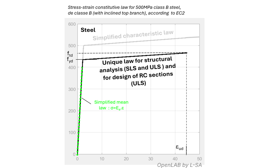
Unlike concrete, steel behaviour shows much less variability, so Eurocode adopts a single behaviour law for steel, used in both structural analysis and cross‑section design.
To remain logically consistent with the concrete approach, one could have expected a mean steel law for structural analysis (e.g. using the characteristic simplified law), and to keep the design law only for ULS section design.
Material behaviours assumed reversible
In the deflection calculation of a continuous beam, one studies various load cases, computes moments, evaluates the cracking state of sections, then the deflections, crack widths, etc.
We therefore assume that, from one load case to another, some sections may return from the “cracked” state to the “uncracked” state, as if cracks not only closed but re‑bonded as if they had never existed. Everything is treated as if cracking were reversible.
At both SLS and ULS, each load case is computed as if no previous load case had occurred. EC2 justifies this by stating: “The effect of prior loading may be neglected and actions are assumed to increase monotonically” (§5.7(3)).
The same applies to concrete and steel stresses.
When variable loads move, previously plastified zones of concrete or steel may return to an elastic state, following the same path backwards as forwards (green curves below).
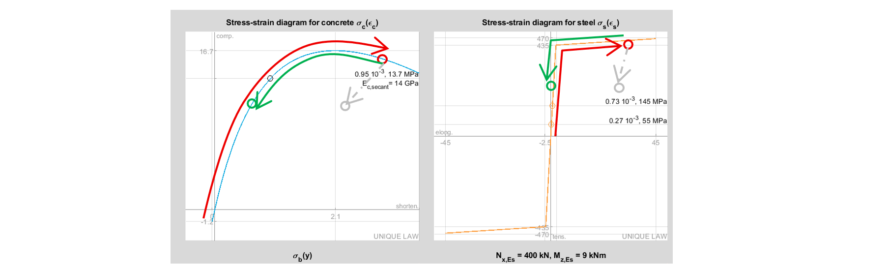
Thus, we do not model true plasticity of the structure but rather the nonlinearity of material laws governing nonlinear elastic behaviour.
Two points are relevant here:
- Characteristic and ultimate combinations are assumed to occur rarely in the life of the structure, so ignoring the history of prior ULS and characteristic loadings is reasonable.
- For cracking, however, one could determine the maximum cracking state for each section under all quasi‑permanent load cases, which occur frequently in practice, and assume at least that level of cracking for all other combinations.
In the next article, we examine more broadly the case of hyperstatic structures and the modelling processes possible under Eurocode 2 : Hyperstatic Structures : the Unique Deformation‑Compatible Solution