
 FR
FR 
Introduction to the MG1 General Method of Eurocode 2 for the Design of Concrete Columns: Foundations, Usage Limitations, and Key Points of Attention.
The general method for column design according to Eurocode 2, and more specifically the simplified option of this method, referred to as MG1 in this document, is an important everyday tool for the reinforced concrete structural engineer. It makes it possible to significantly reduce the theoretical complexity of studying a slender reinforced concrete column or wall, by approximating second-order effects.
However, this method has usage limitations and caution points that can sometimes be difficult to master, especially since spreadsheet implementations—commonly used in design offices—may hide certain important concepts.
This four-part dossier offers a review of the different calculation steps of the general method, with a focus on various influential aspects. This Part 1 provides a reminder of the fundamentals of the general method.
Predicting the Buckling Loads of Columns Using M.P. Faessel’s Method
In September 1968, ITBTP Journal No. 249 introduced M.P. Faessel’s method in France. This method aimed to estimate the ultimate deflection shape of a slender reinforced concrete column in order to derive the second-order effects and the corresponding critical load.
The general method, included today in Eurocode 2, addresses column buckling in the same spirit as Faessel’s approach. It enables a simplified nonlinear analysis, accounting for both geometric nonlinearity and material nonlinearity, to estimate second-order effects more accurately than with the two other Eurocode 2 methods (nominal stiffness and nominal curvature).
More precisely, the general method evaluates strain compatibility at the level of "several" straight sections, and allows a simplified option that performs this evaluation on a single section: the critical section, provided that a reasonable assumption is made regarding the shape of the element’s overall deformation.
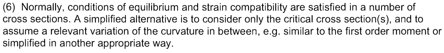
Excerpt from EC2 §5.8.6(6)
In common practice, when referring to the application of the “general method” in the analysis of a slender column or wall, one is most often referring to the simplified option of the general method, reduced to studying a single critical section.
In the remainder of this document, we refer to this simplified option as MG1, and we focus our study on the key caution points inherent to the use of MG1.
Reducing the Problem to the Case of a Mast
MG1 may be presented as an approach that reduces the real structure under study (the column) to the equivalent:
- of a mast (a cantilever column, fixed at the base and free at the top),
- with constant cross-section along its height,
- subject to a single axial load applied at the top (resulting in a constant axial force along the height),
- and presenting an initial inclination defect or a lateral load generating a “reasonable” first-order bending moment.
To establish the equivalence between the real case and the mast model, one evaluates the "buckling length" of the column in its real environment and deduces the equivalent mast length from it.
Once the cantilever mast model is obtained, one studies only the equilibrium of the fixed-base section. If stability of the mast is demonstrated, then the stability of the real column is validated.
The Case of the Mast
We detail here the calculation principle of the theoretical mast.
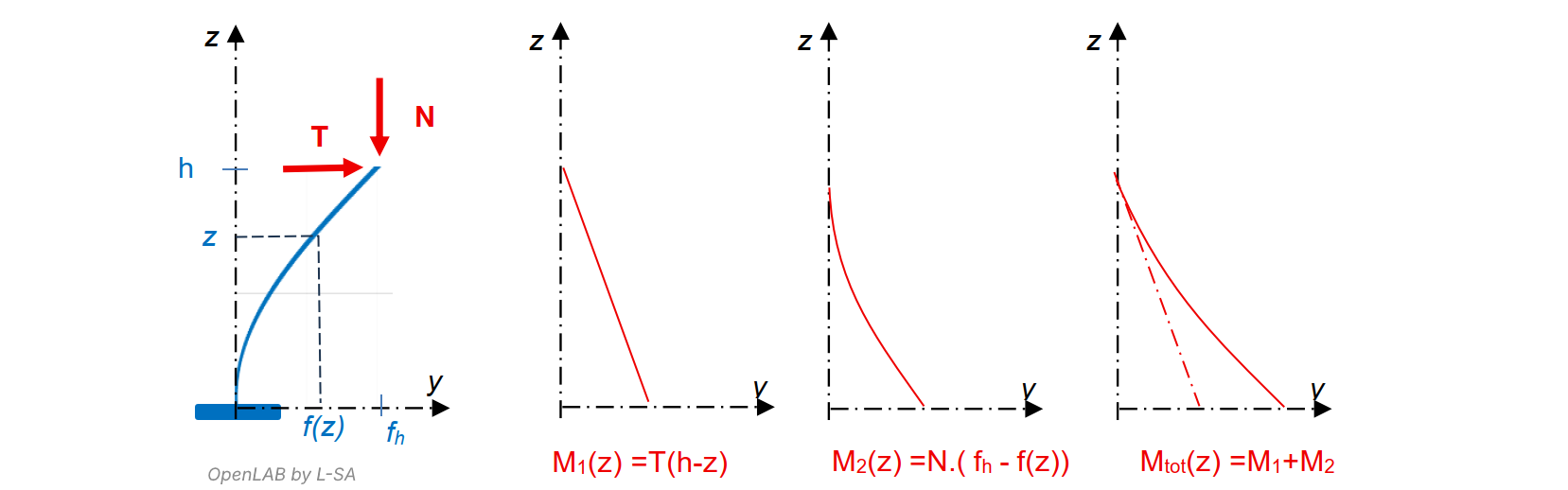
Under the effect of an initial verticality defect or a horizontal load T at the top as shown, the mast undergoes a first-order bending moment M1(z), causing it to deform.
The Second-Order Effect
Because the mast is assumed slender, second-order effects occur, meaning that the deformation of the mast increases the total bending moment Mtot(z) by a non-negligible amount, through the term N·(fh – f(z)).
The deformation f(z) and the total moment Mtot(z) then increase together in an unstable manner until the system reaches equilibrium, if such equilibrium exists, or until failure of the base section where the bending moment is greatest.
Typically in Eurocode 2, the process is sequential: one computes N, T, M along the element (exactly or with valid approximations), then performs reinforced concrete section checks.
Unfortunately, this process cannot be applied here, because forces strongly depend on deformations, and deformations depend on section behavior—forming a closed loop. Solving f(z) directly appears impossible at first glance.
An Assumed Elastic Deflection Shape
When the first-order moment M1(z) is negligible compared to the second-order moment M2(z), when the axial force N(z) is constant along the height, and when the mechanical properties of the sections are constant, bi-symmetric, and remain elastic (linear and uncracked), it can be shown mathematically that the exact deflection shape is a quarter sine wave, expressed as:

MG1 consists of adopting this sinusoidal deformation assumption in situations where we deviate “reasonably” from all these conditions.
Adopting this assumption in reinforced concrete design allows us to predict the deflection at the top of the mast from the curvature at the fixed base.
Thus, we can evaluate the second-order moment at the base as a function of the curvature at that same base section.
This approach eliminates the need to model loads and deformations along the mast, reducing the problem to the sole study of the section at z = 0, the “critical section.”
Numerically, we obtain in two steps the expression of the second-order moment at the base as a function of curvature at that section:

Internal Equilibrium
For a given axial load N, as long as the reinforced concrete section remains elastic, the curvature 1/r is directly proportional to the applied moment: 1/r = (1/EI)·M. As the section cracks and then plastifies, it must bend increasingly to resist a given moment.
The M(1/r) curve of the RC section therefore starts linearly, then curves until reaching the material limits. This curve—depending only on the RC section and not on the mast height or second-order effects—is called the internal equilibrium curve of the critical section.
External Equilibrium
As previously seen, the sinusoidal deflection assumption yields an affine relationship between curvature at the critical section and the induced second-order moment. This relationship depends only on the mast height, axial load, and first-order moment—i.e., external actions—and not on section dimensions, inertia, or material moduli.
The curve Mtot(0) = f(1/r(0)) is therefore called the external equilibrium curve of the critical section.
The Stable Equilibrium Point
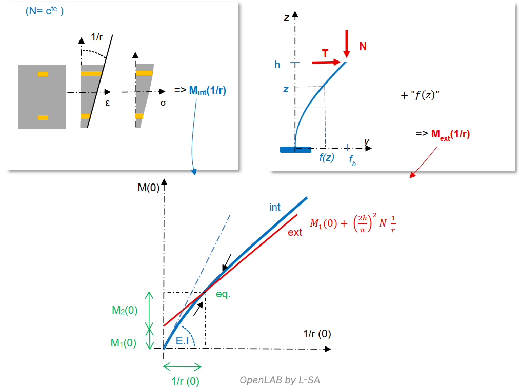
Plotting the internal and external equilibrium curves on the same graph makes it possible to determine whether equilibrium exists and to solve the mechanical problem. When loading begins, curvature 1/r is zero, the external moment Mext exceeds the internal resisting moment Mint, and the mast begins to bend (1/r increases) until reaching a curvature where Mint exactly equals Mext. At this point, equilibrium is achieved.
The Critical Axial Load N
When N increases, the internal equilibrium curve Mint “shrinks” because material plastification increases, and the external equilibrium curve Mext rises and becomes steeper. One may determine the limiting N for which the two curves are tangent: this corresponds to the mast’s critical load Ncrit.
In the remainder of this dossier, we return to a more general framework for applying MG1 to various real column configurations, and we detail the underlying steps.
The next part is dedicated to the assumed deflection shape : General Method of EC2 and Usage Limitations – An Assumption of Elastic Deformation (2/4)