
 FR
FR 
MG1 General Method : Implications of Construction Tolerances on Design, the Impact of Serviceability Deformations, and Verification of Supports.
The general method for column design according to Eurocode 2 is an important everyday tool for the reinforced concrete structural engineer. It makes it possible to significantly reduce the theoretical complexity of studying a slender reinforced concrete column or wall, by approximating second-order effects.
However, this method has usage limitations and caution points that can sometimes be difficult to master, especially since spreadsheet implementations—commonly used in design offices—may hide certain important concepts.
This four-part dossier offers a review of the different calculation steps of the general method, with a focus on various influential aspects.This Part 4, the final part of the series, develops several topics often addressed only briefly, such as construction tolerances, serviceability deformations and the justification of second‑order effects.
Back to the previous article : General Method of EC2 and Usage Limitations – Lateral Loads and Support Stiffnesses (3/4)
Using “Physical” Additional Eccentricities
Regarding geometric imperfections, Eurocode 2 proposes integrating an accidental eccentricity in the form of an inclination or positioning error of the column.
However, the exact formulation in the Eurocode raises a difficulty: using the expression ei = θi·l0/2 makes ei depend no longer on the real height Lreal but on Lmast (= l0/2).
Thus, the notion of geometric imperfection, which is a “physical” construction tolerance issue related to formwork and reinforcement placement on site, becomes tied to a parameter of the equivalent mast, which is a “fictitious” notion arising from the engineer’s calculation.
To illustrate this issue, consider a 5 m column. Regardless of its boundary conditions, the construction crew will use the same formwork and will be subject to the same execution standards and tolerances.
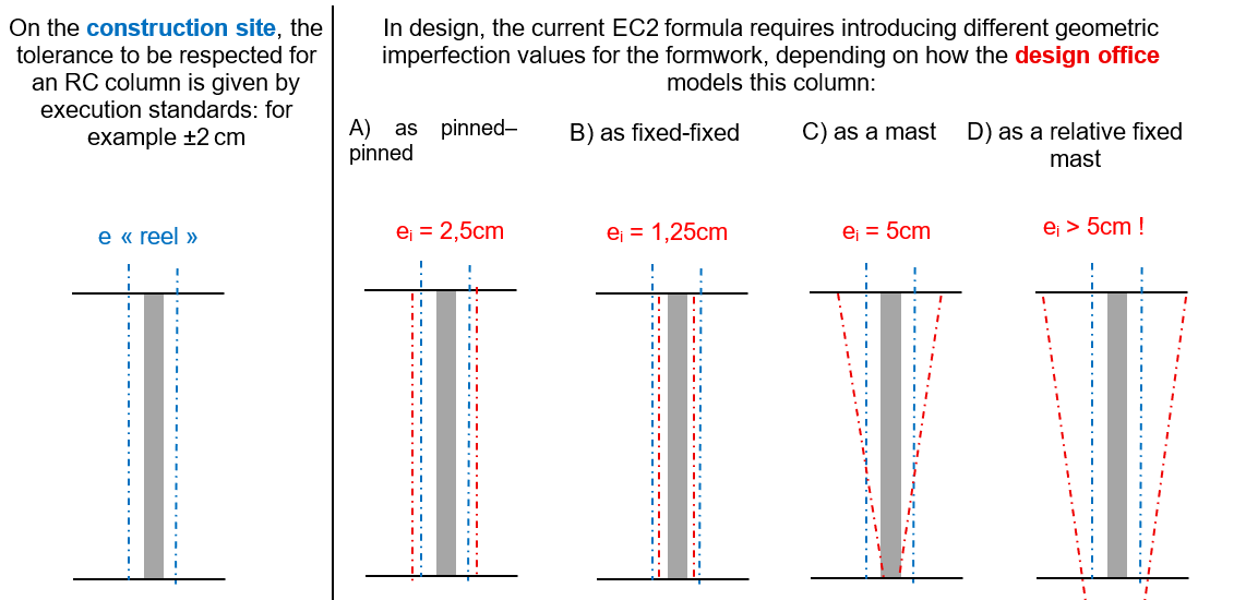
To resolve this contradiction, an alternative expression may be proposed as follows:
- ereal,add = max(2 cm, θi·Lreal) → a “physical” additional eccentricity linked to execution tolerances
Consequently, the eccentricity entered into MG1 would be:
emast,add = max(2 cm, θi·Lreal) · Lmast / Lreal
Transmitting Second-Order Effects to the Supports
Once the column design is completed, the transmission of second‑order effects to its supports, both at the top and bottom, must also be considered.
Unfortunately, spreadsheet implementations of MG1 may obscure this aspect and may not explicitly provide second‑order reactions transmitted to the supports of the real structure.
Consider the simplest case of an industrial column embedded into a foundation block. If the column is designed considering second‑order effects, but the foundation block is designed using only first‑order load paths, the structure will not be fully justified.
Similarly, in the previous example of a mast fixed into a ground beam, the second‑order moment from the column must be included in the design of the beam, even if it is subjected to simple bending or tension–bending. These second‑order effects, which produce imposed moments at the beam supports, must be included for both possible buckling directions and for any additional eccentricity. After the beam is designed, its stiffness—initially assumed—should ideally be verified.
More generally, in hyperstatic or partially fixed support configurations, determining the second‑order forces to be transmitted to the supports—top beam, bottom beam or ground beam, diaphragm, slab, pile, footing—requires applying the previously established theoretical path in reverse to ensure global consistency.
Checking the Magnitude of SLS Horizontal Deformations
The Deformation of a Slender Structure
Although EC2 gives limited guidance on deformation or displacement limits for walls or columns, the SLS deformation of a slender structure (tall wall, slender façade column, bracing mast) may in some cases govern the design more than resistance, similar to the deflection criterion used for slab thickness.
Which Deformation Criteria Should Be Used?
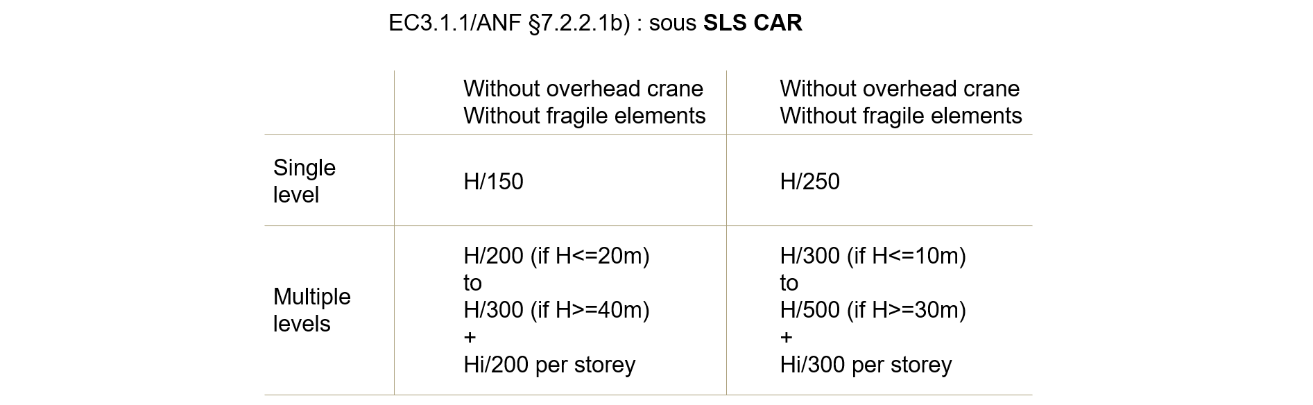
Based on EC0 and EC3 §1.1/NA, one may adopt a criterion of H/150 at mid‑height for a “braced” column or wall at characteristic SLS, and H/250 at quasi‑permanent SLS by analogy with beams and slabs. Similarly, displacements at the top of bracing columns in frames should satisfy these limits, just as in steel structures:
How to Calculate SLS Deformations for a Slender Structure?
Regarding second‑order effects, EC2 states they may generally be neglected if they represent less than 10% of first‑order effects (§5.8.2(6)).
At SLS, they are traditionally neglected, and similarly, geometric imperfections may also be ignored (§5.2(3)).
However, geometric imperfections exist just as much at SLS as at ULS, and it is not always obvious that second‑order effects at SLS will remain under 10%.
Consequently, explicitly checking SLS deformation may sometimes be the simplest solution, using the same structural model as for ULS, after adjusting both loading and material behaviour laws.
Indeed, according to EC2 logic, deformation checks should use mean concrete behaviour laws (and not the more conservative design laws), including tensile strength and progressive cracking where possible, to obtain the most “realistic” deformation estimate to compare with the SLS criteria.
Conclusion of the Analysis
The general method for column design according to Eurocode 2, and more specifically its simplified option MG1, is an important daily tool for reinforced concrete structural engineers. It significantly reduces the theoretical complexity of studying a slender reinforced concrete column or wall by incorporating second‑order effects in a simplified way.
By reducing the full analysis of such an element to the study of a single critical section,
the method allows a broad range of practical cases to be handled beyond the nominal curvature and nominal stiffness methods also provided in EC2, while remaining reasonably simple.
However, MG1 presents several important caution points, particularly since spreadsheet implementations may hide key aspects.
This article has highlighted various caution points of MG1, examining successively:
- the sensitivity of the result to the choice of a relevant deformation shape assumption (sinusoidal or parabolic) and the criteria that validate or invalidate the sinusoidal assumption,
- the challenge of determining the “correct” first‑order bending moment, especially in hyperstatic or partially fixed configurations,
- the caution required when evaluating partial support stiffnesses,
- the need for defining a geometric imperfection consistent with construction tolerances,
- the risk of forgetting the transmission of second‑order effects to the supports,
- and the importance of SLS deformation, which may sometimes govern the design.
The integral general method may be a simpler solution to handle and master in certain cases.
For more information on this topic, see the following two articles:
- An Integral General Method (IGM) in accordance with Eurocode 2, which introduces the strengths of this method, and
- Design of a Mast Using the EC2 General Method – Configuration and Optimisation, which presents a concrete example first treated using the simplified general method (MG1), then using the integral general method (IGM).