
 FR
FR 
Analysis of concrete shrinkage, the induced self‑stresses, the differences with thermal effects, and the conditions for applying EC2 formula (7.21).
This article examines the mechanical behaviour of reinforced concrete subjected to shrinkage, highlighting the fundamental differences between shrinkage and thermal effects, and introducing the notion of self‑stresses that develop within the section.
It then analyses how the constitutive laws of concrete and steel are modified and how the mechanical diagrams of a reinforced‑concrete section (geometry, strains, stresses, internal forces) evolve under shrinkage.
Finally, the article clarifies the conditions under which Eurocode 2 formula (7.21)—used to estimate the curvature of a flexural member due to shrinkage—can be validly applied.
This contribution forms the third part of the series “Axial behaviour of flexural reinforced‑concrete elements” (3/4).
Back to the previous article: Axial analysis, concrete shrinkage and thermal expansion in flexural structures – thermal expansion and thermal gradient (2/4)
The concrete shrinkage phenomenon
Concrete is a mixture of water, aggregates and cement. Cement, in the presence of water, undergoes a chemical exothermic reaction leading to its setting (a few hours) and then hardening (a few days), thereby forming a continuous and monolithic matrix linking the aggregates.
The chemical reaction occurs with a volume reduction, a phenomenon called autogenous shrinkage.
For practical mixing purposes, water is added in excess compared with the stoichiometric needs of the chemical reaction. This excess water must eventually leave the material over time, causing an additional volume reduction called desiccation shrinkage or drying shrinkage (spanning months or years).
Beyond ambient temperature and humidity conditions, the kinetics of shrinkage depend on the path length of water inside the element before evaporating at the surface. It therefore depends on the geometry of the element via its “mean radius”.
Shrinkage effects and thermal effects: completely different mechanics
In mechanical modelling, it is common practice to represent shrinkage effects as an equivalent temperature decrease when reinforced concrete is modeled as a homogeneous, elastic, and uncracked material.
This analogy offers a clear practical advantage: thermal load cases are available in most finite element software, which makes implementation straightforward.
However, this simplification has major limitations. It does not allow one to account for:
- the influence of reinforcement,
- nor the effect of cracking on the stress state of reinforced concrete structures.
Yet, in the analysis of shrinkage effects:
- cracking plays a determining role in the distribution of internal forces (N, M),
- reinforcement, apart from joints, is the primary lever available to engineers to control these effects.
Furthermore, this approach does not allow for a proper evaluation of the impact of shrinkage on element curvatures, and therefore on long-term deflections. In particular, it does not make it possible to reproduce phenomena such as that described by Equation 7.21 of Eurocode 2.
In reality, concrete shrinkage follows a mechanical behavior that is fundamentally different from that of thermal effects. Unlike thermal strains, shrinkage applies exclusively to the concrete, while the steel reinforcement is not subjected to this imposed deformation.
Thus, independently of external actions (bending moment or axial force), shrinkage generates internal self-equilibrating stresses:
- the reinforcement, which resists shortening, is subjected to compression,
- the concrete, restrained by the reinforcement, is subjected to tension.
These internal interactions lead to a reduction in the “visible” effects of shrinkage at the global analysis level (internal forces and measurable deformations), while also generating additional specific strain and stress states.
The remainder of this article therefore proposes a more accurate approach to modelling reinforced concrete structures subjected to shrinkage, based on a local description of the constitutive behavior of both concrete and reinforcement.
Considering concrete shrinkage at the local level
Modification of material constitutive laws
The effect of shrinkage is treated locally through constitutive laws. The principle is similar to that of thermal effects (see previous article), with two major differences:
- The steel constitutive law is unaffected.
- The concrete constitutive law shifts only to the right. Shrinkage necessarily induces “shortening.” We write σ = f(ε − εc), with εc > 0.
Generation of self‑stresses
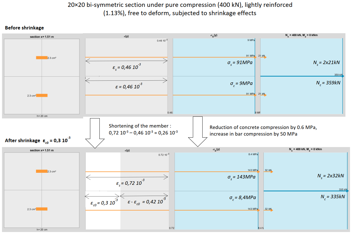
Below is a bi‑symmetric, fully compressed section, lightly reinforced, freely axially dilatable, subjected to a shrinkage strain of 3×10‑4. We observe that the concrete does not shorten by 3×10‑4, but only by 2.6×10‑4, because part of the shrinkage is restrained by the reinforcement, whose compressive contribution increases, while concrete compression decreases.
The curling phenomenon under a shrinkage gradient
Consider the same concrete element, now permanently immersed on its upper surface and exposed to air on the underside, while remaining freely axially dilatable and isostatic in bending. The concrete cannot undergo shrinkage on the immersed surface. Assuming a linear shrinkage distribution, we obtain a curling phenomenon, the element bending toward the side where shrinkage is prevented.
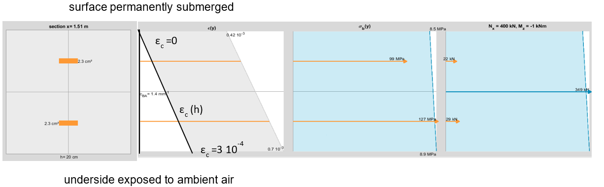
Note: The small moment of 1 kNm is a second‑order effect resulting from the slender column model used for this example. For an isostatic element in bending, a shrinkage gradient does not produce a first‑order bending moment.
Evaluating curvature due to shrinkage
Simplifying the study of shrinkage effect
Let us return to the assumption of uniform shrinkage across the height of a section: εc(h) = εc = 3×10‑4.
In what follows, we assume that structural analysis has provided the bending moment M and axial force N acting on the reinforced concrete section, and that {M, N} is not affected by shrinkage‑induced curvature or elongation. In other words, the member is isostatic in bending, freely axially dilatable, and free from second‑order effects: assumption {H1}.
If the steel remains elastic after shrinkage (assumption {H2}), we can isolate shrinkage and return to the usual RC‑section study by performing a change of reference frame.
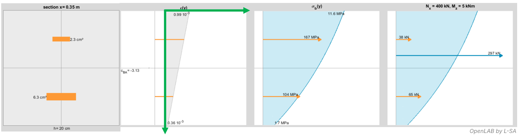
Consider a simply supported beam subjected to N = 400 kN (compression), M = 5 kNm at midspan, and shrinkage. Let us examine the midspan section:
We define εfictitious = εreal − εc.
In this fictitious frame:
- For concrete: σ = f(εfictitious) as if no shrinkage existed
- For steel: σ = Es(εfictitious + εc) = Esεfictitious + Esεc
Thus, it is as if the steel had been prestressed (in compression) before casting, by an amount Esεc.
The corresponding effects are:
Ncs = Σ Asi Es εc > 0
Mcs = Σ(h/2 − yi) Asi Es εc
Let As,tot = Σ Asi, Ss,tot = Σ(h/2 − yi) Asi, αe = Es/Eb.
We obtain:
Ncs = As,tot Es εc
Mcs = Ss,tot αe Ec εc
The study of the RC section subjected to {M, N} + shrinkage becomes equivalent to studying the section under the fictitious loading {M − Mcs, N − Ncs} without shrinkage.
We note that shrinkage:
- reduces concrete compression (−Ncs < 0)
- increases bending in concrete (−Mcs > 0)
After solving the fictitious section, we return to real values using:
Concrete:
- σcreal(h) = σcfictitious(h)
- εreal(h) = εfictitious(h) + εc
Steel:
- σs,ireal = σs,ifictitious + As,i αe Ec εc
- εs,ireal = εs,ifictitious + εc
We must also check εs,ireal < fyk/Es to validate {H2}.
Numerical example
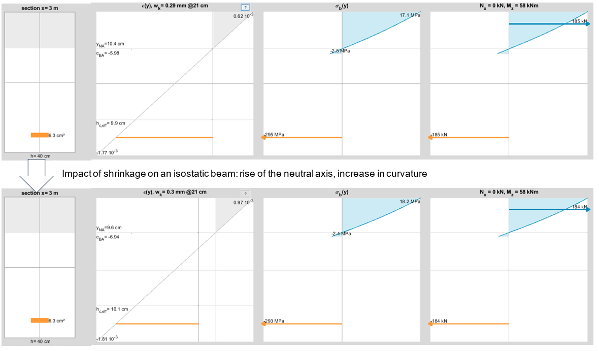
Consider a section of a simply supported beam under N = 0, M = 58 kNm.
We apply shrinkage: εc = 3×10‑4.
Now place ourselves in the “fictitious” case:
- Nreal = 0 → Nfictitious = −37.8 kN
- Mreal = 58 kNm → Mfictitious = 63.7 kNm
- εc,real = 3×10‑4 → εc,fictitious = 0
Results match exactly (up to rounding):
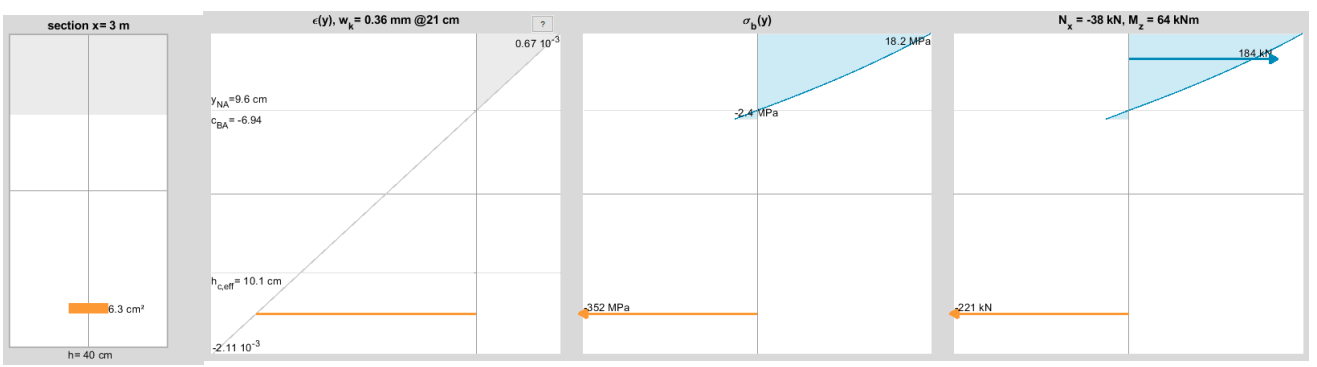
In the above example, additional curvature due to shrinkage is 9.6×10‑4 m‑1.
The Eurocode 2 formula for shrinkage‑induced curvature
Shifting the static moment to the centroid
Consider the following bending‑compression case.
Section 20×40 cm, reinforcement 2HA20 at d = 35 cm, Ecm = 28 GPa (thus αe = 7.1), subjected to N = 500 kN and M = 63 kNm before shrinkage.
As seen earlier, shrinkage is represented by the complementary force set −{Ncs, Mcs}. We separate the two load sets and place −{Ncs, Mcs} at the cracked‑section centroid “CG”.
The centroid is located at yCG = 0.15 m.
For shrinkage effects, Ss,tot becomes:
Ss,tot = Σ(yCG − yi)Asi
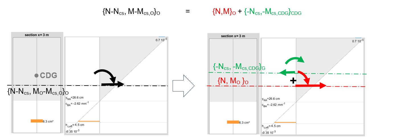
Consider the effect of −Ncs alone applied at the centroid. Two common cases arise:
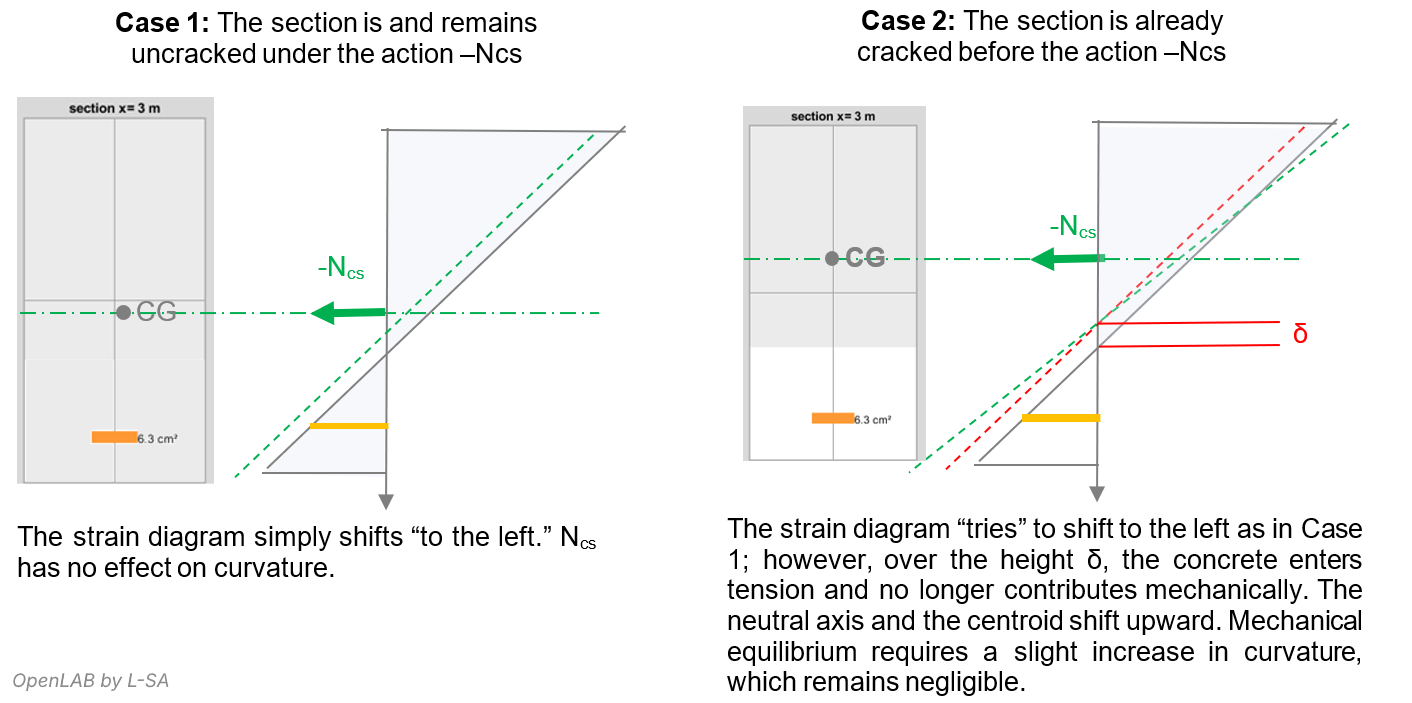
Placing the load at the centroid minimizes the curvature influence of Ncs. Therefore, −Mcs is the only component significantly affecting curvature.
Since curvature = M / (Ec I), shrinkage curvature is:
(1/r)cs = Ss,tot αe / I · εc
This is EC2 formula (7.21).
Applying it yields (1/r)cs = 9.4×10‑4 m‑1, matching the earlier result.
What if −Ncs or −Mcs causes cracking?
If shrinkage loads cause the section to crack, EC2 formula (7.21) no longer applies.
Cracking causes curvature to increase far beyond the formula’s estimation.
EC2 recommends fictitiously considering:
- fully uncracked beam → (1/r)cs,I
- fully cracked beam → (1/r)cs,II
Then:
(1/r)cs = ζ(1/r)cs,II + (1−ζ)(1/r)cs,I
Thus shrinkage‑induced curvature is underestimated in zones where shrinkage causes cracking.
Conditions for applying the formula
The conditions for applying EC2 formula (7.21) are:
- Uniform shrinkage across the section height
- Global loading {M, N} must remain unaffected by shrinkage curvature (assumption {H1}):
- formula cannot be used for continuous beams
- cannot be used for second‑order effects
- Steel must remain elastic (assumption {H2}), therefore formula cannot be used at ULS.
- Shrinkage effects −{Ncs, Mcs} must not change the cracking state established under {M, N}.
Thus, EC2 formula is only strictly valid if shrinkage does not increase cracking along the beam.
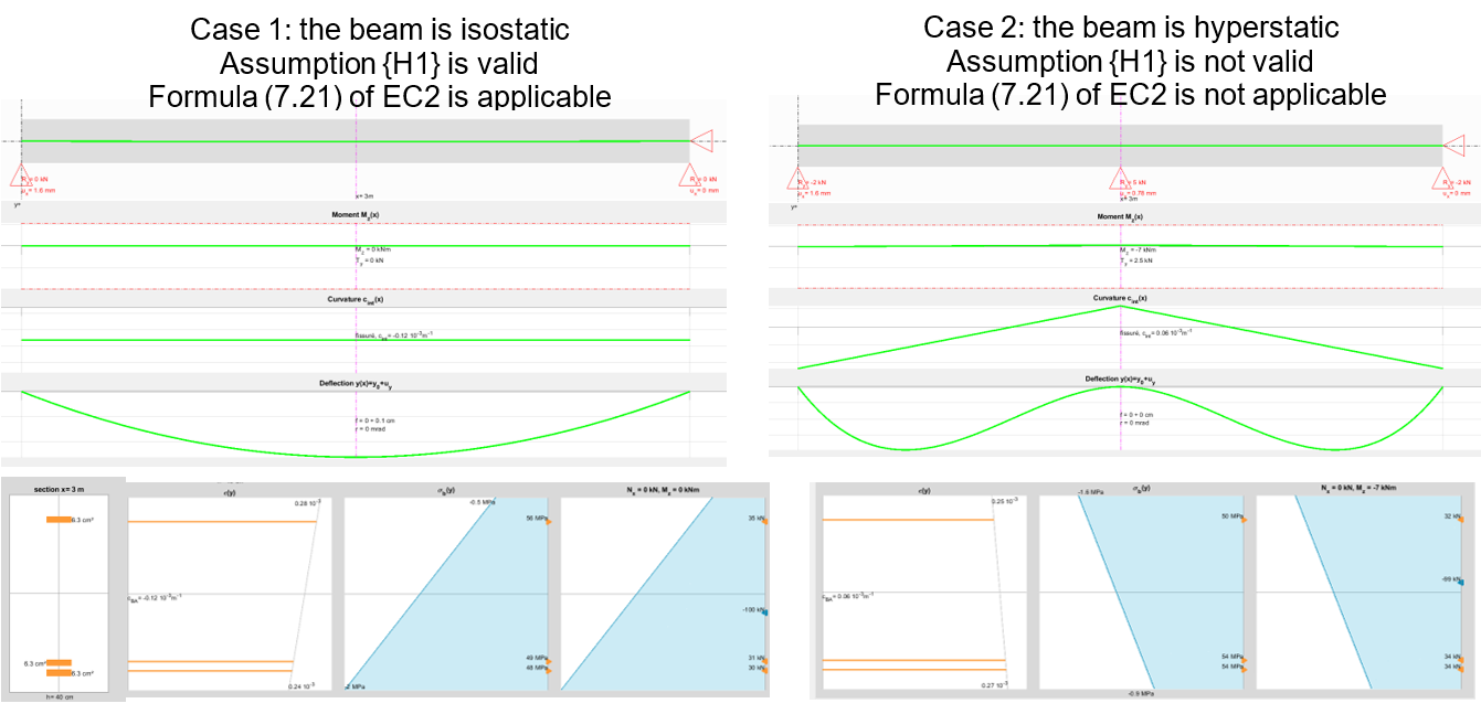
Let us revisit assumption {H1}:
Consider a 20×40 cm beam with reinforcement 2HA20 top, 4HA20 bottom, under shrinkage 3×10‑4.
Case 1: simply supported → isostatic → formula valid → constant curvature → downward bending.
Case 2: add a middle support → hyperstatic → compatibility imposes M = 7 kNm at support → curvature is not constant → formula invalid.
In the next article, we examine situations where shrinkage must be considered, the cases of concomitance with thermal effects, and the influence of cracking:Axial analysis, concrete shrinkage and thermal expansion in flexural structures - Concomitance and impact of cracking (4/4)