
 FR
FR 
Synthesis of simultaneous axial effects: shrinkage, thermal actions, gravity‑induced elongation, cracking, and the limitations of elastic analyses.
This final part broadens the analysis of axial effects by considering the concomitance between shrinkage, thermal expansion and gravity‑induced elongation, as well as the impact of cracking.
The article highlights several points of vigilance regarding the elastic structural analysis of axial effects, and proposes that shrinkage studies should systematically include the effect of gravity‑induced elongation, and that thermal analyses at the characteristic SLS should jointly include shrinkage + gravity effects.
It constitutes the fourth part of the series “Axial behaviour of flexural reinforced‑concrete elements” (4/4).
Back to the previous article: (3/4) – Calculation of concrete shrinkage effects
Elastic structural analysis: a false friend for thermo‑mechanical behaviour in reinforced concrete?
Elastic bar, plate and shell models are important tools in a structural engineer’s daily practice. However, when used to study thermal effects and shrinkage, they must be used with caution to produce meaningful analyses.
As explained in the first article of this series, it should be recalled that such models do not allow treatment of axial strain compatibility in bars, nor compatibility of flexural deformations. Moreover, they do not take second‑order effects into account.
thermal expansion effects
If axial restraints are included in such models to determine the internal forces generated by thermal expansion, it is necessary to consider, during post‑processing, the compression “offset” already present in the reinforced‑concrete structure under those same axial restraints, even before thermal effects occur, due to gravity loads.
Furthermore, the stresses induced by restrained thermal expansion depend on the ES product; the modulus E and its creep coefficient must therefore be estimated, as well as the reduced steel area S due to flexural cracking, in a manner different from (and more penalising than) what applies to I.
The same applies to evaluating thermal‑gradient effects: a fictitious reduction of the Young’s modulus must be applied in order to obtain an EI product of the correct order of magnitude. The modulus reduction may range from a factor of 4 to 6.
Just as it is difficult to obtain a correct evaluation of beam or slab deflections in reinforced concrete using an elastic model, it is often difficult to obtain a correct evaluation of thermal effects.
shrinkage effects
In terms of mechanical modeling, concrete shrinkage is treated differently from thermal effects, because it applies exclusively to the concrete and not to the reinforcing steel. In practice, this means that the effects of shrinkage cannot be rigorously approximated by a temperature decrease in an elastic beam model. Such a representation would amount to assuming that the steel undergoes the same shrinkage as the concrete.
Independently of any stresses related to the bending moment and the axial force applied to the section, the phenomenon of concrete shrinkage generates self-induced stresses in both the concrete and the steel, modifying the forces and deformations “observed” at the scale of structural analysis.
Consequently, the curvatures and deflections induced by shrinkage cannot be modeled in elastic structural analyses, and, as a result, the internal forces induced in statically indeterminate systems under shrinkage effects can hardly be represented either (see the end of the previous article).
Concomitance of shrinkage – creep – thermal effects – gravity‑induced elongation
Beyond all these elements, it should be generally considered in the analysis that thermal expansion, shrinkage, creep and gravity‑induced elongation do not occur in isolation but concurrently, and are strongly affected by cracking.
When should shrinkage effects be taken into account?
As with thermal effects, the deformation magnitudes involved in shrinkage phenomena (0.3 × 10‑3) are small compared to the strain ranges of materials allowed at ULS. Eurocode 2 §2.3.2.2 therefore states that shrinkage effects should be considered only at SLS and neglected at ULS in the general case.
However, Eurocode 2 specifies that the effect of shrinkage at ULS must be examined when it may have a significant impact on second‑order analysis, or when deformation compatibility must be checked. The question then arises as to which practical method should be used for these verifications, since the only approach proposed by Eurocode 2, formula (7.21), applies at SLS and is intended solely for isostatic deflection calculations. Furthermore, standard elastic bar models do not allow implementing deformation compatibility in structural analysis, as seen earlier.
In certain simplified cases, the general integral method (MGI) can offer a possible solution.
Unlike thermal effects, concrete shrinkage is a phenomenon that occurs in a systematic and permanent manner and will be present during a significant part of the structure’s service life.
The period during which shrinkage has not yet occurred can be likened to a temporary phase at the beginning of the structure’s life, similar to the construction phase. Statistically, it is reasonable to assume that occurrences of “characteristic” and “ultimate” load combinations will take place only once shrinkage has occurred.
If a calculation method enables simple consideration of the phenomenon, it would therefore appear relevant to systematically include shrinkage in all SLS checks (and possibly ULS), in order to obtain deformation and stress evaluations that better reflect reality.
This proposal also applies to creep, particularly under quasi‑permanent loads. Since creep is present during a significant portion of the structure’s life, it would be reasonable to systematise its consideration in reinforced‑concrete checks at SLS and ULS.
When thermal effects occur, shrinkage and creep have already happened!
In particular, when thermal effects occur in a reinforced‑concrete structure—especially under “rare” load situations such as the characteristic SLS—it is reasonable to consider that concrete shrinkage and creep under quasi‑permanent loads have already taken place.
For the same reasons as above, it would therefore be reasonable to systematically study thermal effects in conjunction with shrinkage and an appropriate creep coefficient.
In the illustration below, a 20×40 cm beam section is considered, subjected at SLS to a normal force of 400 kN and a bending moment of 64 kNm, in the presence of a thermal action corresponding to a 30 °C increase at the top surface and a 10 °C decrease at the underside. When this situation occurs, shrinkage and creep have already taken place: the concrete has creeped with a factor of 2 and experienced a shrinkage of 3 × 10‑4. The mechanical diagram of the section is as follows:
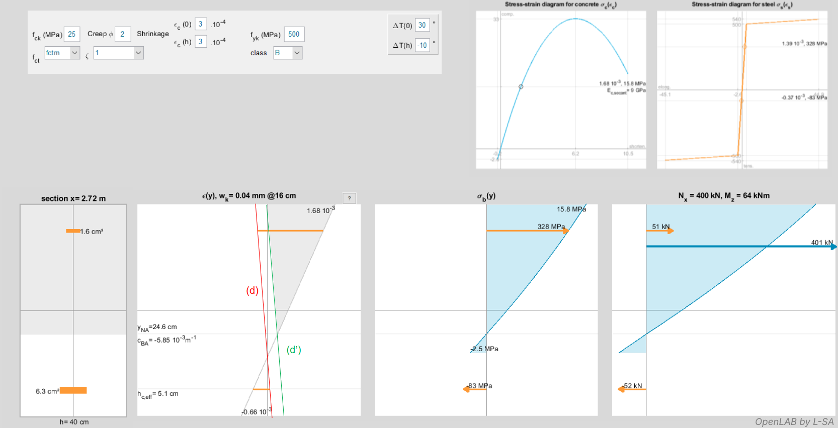
The line (d) in the strain diagram is used as the basis for calculating steel stresses: since steel is only sensitive to thermal variation, the line passes through ε(0) = −30 × 10‑5 = −0.3 ‰ at y = 0, and ε(h) = −(−10 × 10‑5) = 0.1 ‰ at y = h.
The line (d’) is used as the basis for calculating concrete stresses, since concrete is sensitive to both phenomena. The line (d’) thus passes through ε(0) = −30 × 10‑5 + 3 × 10‑4 = 0 at y = 0, and ε(h) = −(−10 × 10‑5) + 3 × 10‑4 = 0.4 ‰ at y = h.
Digression: SLS beam calculation using the general integral method (MGI)
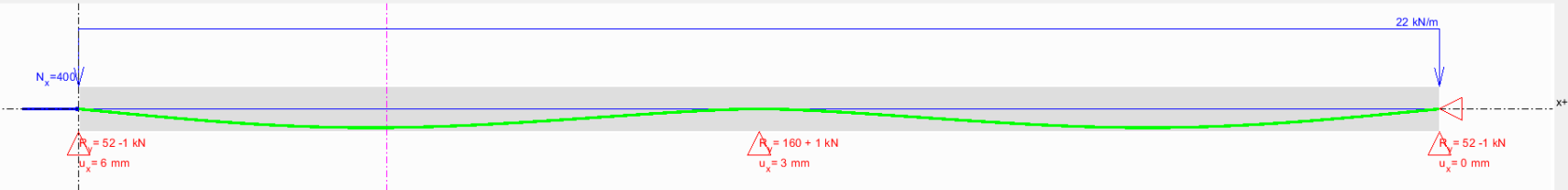
The previous RC section belongs to the beam shown below, assumed to be reinforced identically along its entire length. This beam is therefore subjected to a lateral load of 22 kN/m, a normal force of 400 kN, a thermal effect of +30 °C at the top and –10 °C at the bottom, a shrinkage of 3 × 10‑4 and a creep coefficient of 2.
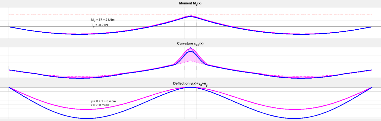
The following curves show bending moment, curvature and deflection under three different calculation modes. They are presented in pairs to illustrate how the responses evolve between the calculation modes.
* Purple curves: results obtained by assuming uncracked sections in the structural analysis and without enforcing deformation compatibility. This corresponds to the Eurocode 2 calculation process: [1] structural analysis then [2] section checks (see the first article of this series).
The notion of curvature is therefore split: on one hand, the external curvature (dashed) obtained by structural analysis [1]; on the other hand, the internal curvature (bold) required for moment equilibrium in the RC section model [2]. The discrepancy between external and internal curvature is shown in purple and represents the incompatibility zone.
* Blue curves: mechanically exact results, where compatibility is ensured at every point along the beam. Moving from the purple to the blue curves requires the structural analysis to account for the need for greater curvature near supports and in spans (in practice, the sections cannot remain uncracked).
This leads to a 40% increase in deflections (from 1 cm to 1.4 cm), while moment redistribution remains negligible (57 kNm to 59 kNm), as cracking occurs both at the support and in the span. In the blue curves, external and internal curvatures merge into a single curve, except at the support where the regulatory curvature‑limiting effect of EC2 appears.
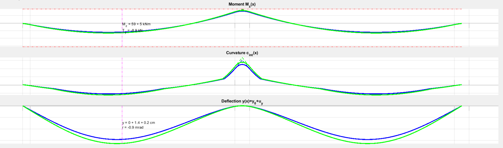
* Green curves: also mechanically exact, but including the second‑order effects induced by N. These effects are far from negligible, impacting both the bending moment (59 → 64 kNm) and deflection (1.4 → 1.6 cm).
Mitigation of shrinkage effects through cracking
The general integral method (MGI) also makes it possible to analyse how section cracking can reduce shrinkage effects. The table below illustrates the behaviour of a given continuous slab under various loading situations and different axial configurations.
The results of the elastic approach are also shown in the first column for reference.
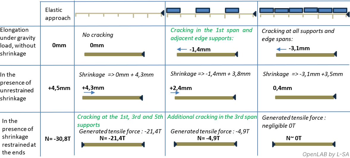
These results clearly show how cracking in flexural members, together with the consideration of gravity‑induced elongation, significantly affects the evaluation of shrinkage‑induced internal forces.
This also raises the question of how to incorporate “cracking memory” in reinforced‑concrete structures:
Currently, when calculating the deflection of a beam or slab, the cracking ratio ζ is evaluated at each location only as a function of the load case under consideration. It is as if, after being loaded and cracked, a slab could return to an uncracked state for the next load case.
An alternative approach could consist in determining the maximum cracking ratio ζ reached at each location across all relevant load cases, and then calculating deflections under each load case assuming that this maximum cracking state remains. This cracking state could then be integrated into the analysis of shrinkage and thermal‑expansion effects.
This series on the “axial behaviour of flexural reinforced‑concrete elements” concludes with an opening toward several complex but interesting topics. Please feel free to comment, contribute or suggest corrections in the discussions associated with this article (OpenLAB members). Thank you.