
 FR
FR 
The behaviour of reinforced concrete flexural structures is intrinsically non-linear and depends on cracking and the progressive plastification of sections.
Compared with earlier generation codes (BAEL), Eurocode 2 now benefits from the theoretical contributions required to take these phenomena into account, notably enabling the calculation-based treatment of concrete adaptation, the formation of plastic hinges, moment redistribution, as well as deformation compatibility issues.
Depending on the required level of analysis, the code also allows simplified, regulated methods based on linear-elastic analyses, possibly combined with predefined moment redistributions.
These various approaches provide the calculation framework with a certain versatility and give the engineer a degree of flexibility suited to the diversity of situations encountered in practice.
While simplified analysis methods (§5.4 to §5.6) are widely used in practice, the present study proposes to utilize non-linear methods (§5.7) on simple cases in order to progressively highlight the mechanisms underlying structural analysis according to EC2, and to provide additional insight into linear-elastic analyses and redistribution practices.
In the field of moment redistribution, it can notably be observed that:
- as long as behaviour remains essentially elastic, moment distributions remain close to those obtained from linear-elastic analysis; cracking effects generally lead to limited adjustments that are weakly correlated with reinforcement strategies,
- redistribution phenomena related to reinforcement strategies become significant when sections enter a strongly non-linear domain,
- reinforcement strategy then plays a decisive role in the final distribution of internal forces at ULS, within the framework of concrete adaptation.
- Concrete adaptation according to EC2
- Non-linearity of reinforced concrete structures
- The uniqueness of the “exact” solution
- The principle of concrete adaptation
- Computation of concrete adaptation
- Formation of plastic hinges
- Moment redistribution
- Deformation compatibility
- Support reloading strategies and reinforcement optimization
- “French” practice of moment redistribution at SLS
- Linear-elastic analyses for practical design
- A slab on four supports: linear-elastic analysis vs non-linear analysis
- Conclusion
Concrete adaptation according to EC2
Non-linearity of reinforced concrete structures
The behaviour of reinforced concrete structures is intrinsically non-linear.
For a given loading applied to a continuous beam, the internal forces M(x), N(x), T(x) that develop within a structure depend :
- on the one hand :
- on the composite concrete-steel sections, which are geometrically variable along the beam
- and on the other hand :
- on the progressive cracking of these sections along the longitudinal axis
- on the plastification of each of the two materials: steel and concrete
- on the creep and shrinkage of concrete over time
To these aspects may be added considerations of construction staging or load variations, as well as other particularities not addressed in this presentation.
The uniqueness of the “exact” solution
Compared with the design rules of previous generations, EC2 benefits from numerous theoretical advances enabling a more precise representation of the mechanical behaviour laws of concrete and steel, as well as the progressive cracking of sections.
During structural analysis, these laws can be used through a non-linear analysis (EC2 §5.7) to determine the “exact” internal forces of the system, i.e. those consistent with the adopted behaviour laws, once all the characteristics of the structure are known.

When such a solution exists, it is unique.
In this paper, we focus on the use of this type of analysis for the determination of internal forces in continuous beams, in order to understand the impact of different reinforcement strategies on moment distributions.
The objective is also to relate the linear-elastic structural analyses widely used in practice (linear-elastic analysis with limited redistribution and plastic analysis) to the general philosophy of EC2.
On the accuracy of the solution
The notion of “accuracy” used here should be understood as “complying with all the mechanical laws described in EC2”. Since these laws remain calculation models, accuracy is naturally relative to the code and has no absolute meaning.
The principle of concrete adaptation
When the system is statically indeterminate, several “load paths” are possible for transferring a load to the supports.
For the same structural layout, the internal forces in the beam may therefore be radically different, depending on the reinforcement choices made by the designer.
The elementary example below, of a two-span continuous slab, illustrates this phenomenon through two extreme situations :
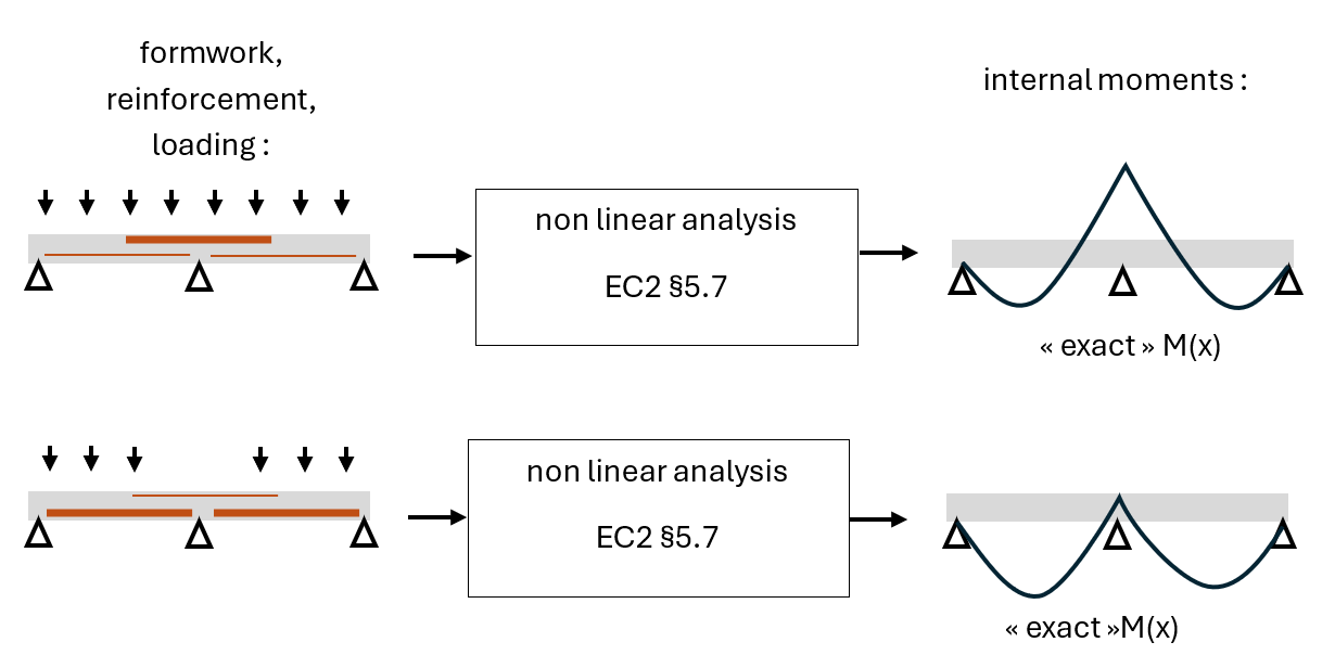
In the first case, the structure has been reinforced according to an “RDM” moment distribution for a three-support beam. The non-linear analysis of the system leads to a solution very close to the shape of the RDM curve of a linear-elastic beam with the same geometry.
In the second case, the structure has been “almost” reinforced as two independent simply supported beams, with however some top reinforcement ensuring continuity. The non-linear analysis of the system highlights cracking followed by significant plastification of the top reinforcement, resulting in a moment distribution M(x) “almost” comparable to that of two juxtaposed simply supported beams.
It can thus be observed that the overall behaviour of the structure strongly depends on the chosen reinforcement strategy, which is often summarised by the idea that “concrete adapts” to the proposed design.
The use of non-linear methods (§5.7) for the analysis of continuous beams offers the advantage of capturing and justifying through calculation this phenomenon of concrete adaptation, by determining the “exact” internal forces obtained as a function of reinforcement, when equilibrium can be established.
Computation of concrete adaptation
To illustrate the previous discussion, we examine in detail the behaviour of the two-span continuous slab mentioned earlier, within the framework of a sensitivity study. We consider:
- a beam (slab) of 100x28cmHT in C25/30,
- continuous over two spans of 7.50m between axes,
- supported on monolithic supports 30cm wide,
- and reinforced with 10HA12 top bars and 6HA12 bottom bars, type HA 500B, running along the entire length (for simplicity).
From this reference configuration, several reinforcement alternatives are investigated, with varying proportions of top and bottom reinforcement.
The structural analysis carried out is of the following type:
- non-linear, in order to determine the “exact” evolution of the moment distribution,
- studied for a single case of uniform loading over the two spans, applied progressively, from p = 5 kN/m² to p = 18 kN/m².
In accordance with EC2:
- the internal forces are calculated based on spans measured between axes,
- support bending moments are limited at the face of the supports.
The span moments Mt and support moments Ma are expressed:
- in kNm,
- and as a proportion of “M0”, where M0 is defined as p × (7.50 – 0.3)² / 8, representing the simply supported moment calculated from spans measured between support faces for a given load.
The curvature along the longitudinal axis is also analysed in order to identify cracked regions and plastified regions of the slab.
The results of this study are presented in the overall figure below:
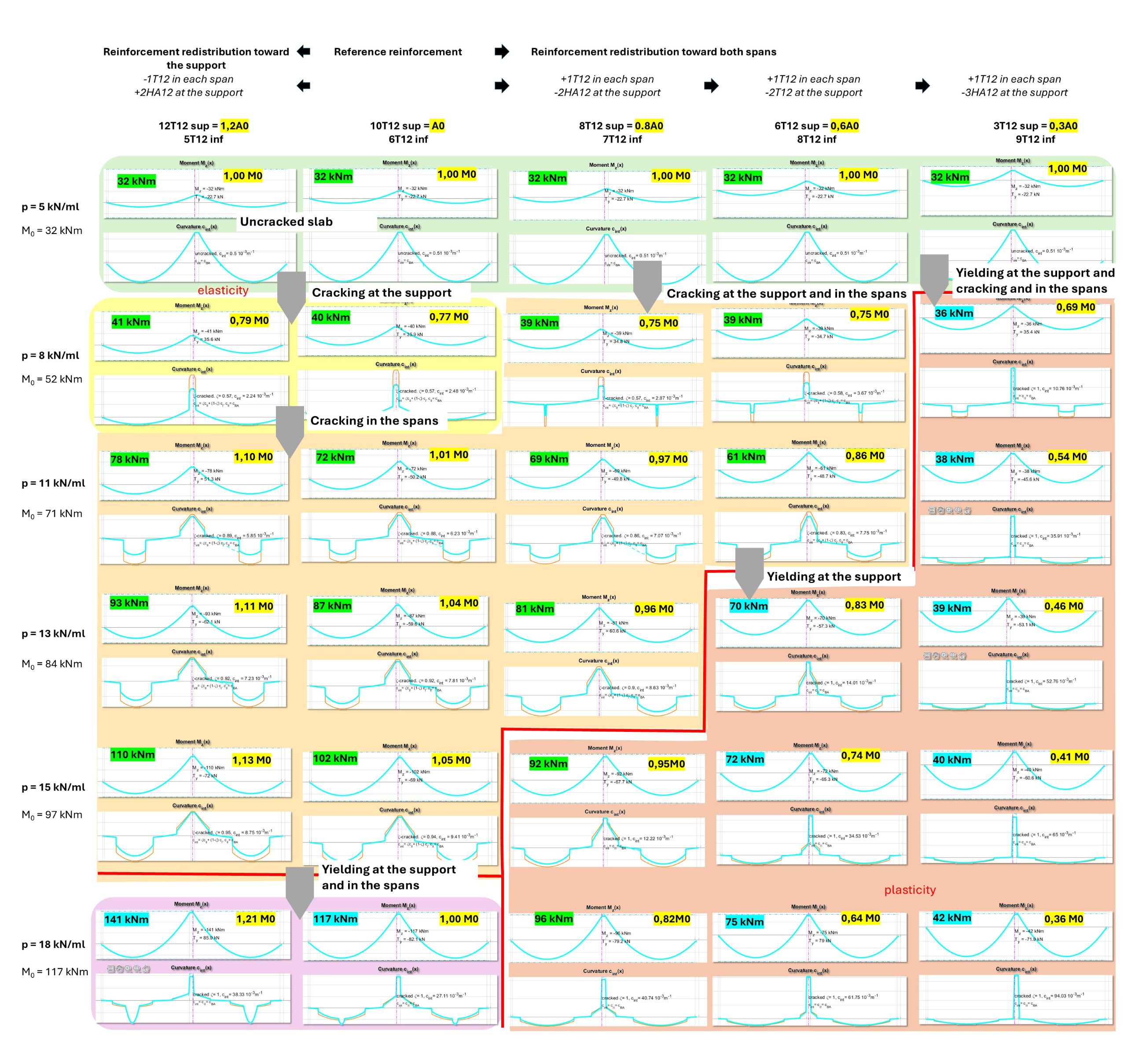
Depending on the reinforcement strategies, and on the progressive cracking and plastification of sections, it can be observed that the moment distribution is highly variable.
Under ultimate loading conditions (last row), the moment distribution “follows” the reinforcement layout: increasing top reinforcement results in a reloading of support moments, whereas decreasing it leads to a redistribution of moments towards the spans.
Formation of plastic hinges
The shape of the curvature diagrams of the slab under the different calculation configurations is worth examining. Let us zoom in, for example, on the configuration p = 18 kN/m² and Aa = 0.6A0:
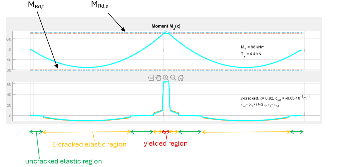
As long as the sections remain within an elastic behaviour regime, whether cracked or uncracked, the curvature remains low and follows a proportional relationship (c = 1/EI · M) with the bending moment.
As the ultimate bending resistance of the section is approached, here near the support, the curvature increases significantly. This reflects the transition of the reinforcement, and potentially the concrete, into a plastic regime.
Over the 30 cm plastified zone near this intermediate support, the curvature reaches approximately 60·10-3 m-1. It can be noted that this value is 6 times greater than the curvature developed in the cracked section within the span, which remains in an elastic regime.
Since the support and span moments are of the same order of magnitude (75 kNm and 88 kNm respectively), the cracked stiffness of the beam appears to be divided by 6 at the support due to plastification.
A curvature of 60·10-3 m-1 over 30 cm results in a significant rotation of the beam equal to 60·10-3 × 0.3 = 18 mrad between the two ends of the plastified zone.
The slab thus behaves as if it were composed of two elastic segments, connected by a plastic segment, transmitting a moment of 75 kNm while “deforming as required”. This is referred to as a plastic hinge in the sense of EC2.
This hinge, which is not strictly point-like but represents a finite zone, can also be observed on the deflection curve, where an almost distinct “angle” forms.
Moment redistribution
The previous study can be advantageously post-processed using a graph showing the support moment as a function of the progressive loading of the slab, for the different reinforcement strategies tested.
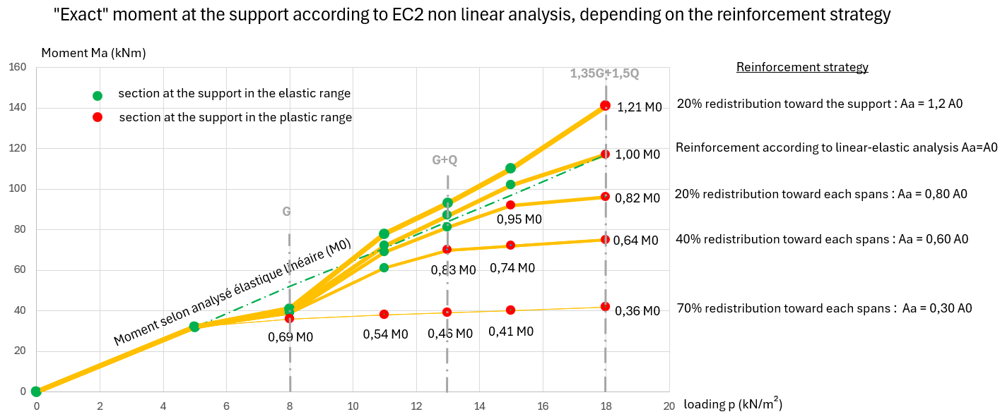
Regarding the possible redistribution of the support moment, these curves tend to highlight the following points:
- As long as the sections remain in an elastic regime, the moment distribution remains within a band very close to linear-elastic analysis.
- Under low SLS loading (under G), a 25% redistribution is observed in this example, due to the fact that support sections crack earlier than span sections.
- This redistribution value is independent of the reinforcement distribution.
- As the SLS loading increases, the 25% redistribution disappears once the spans also crack significantly.
- Under high SLS loading, a slight influence of reinforcement distribution on moment distribution can be observed, but it remains marginal.
- Under ULS loading, when sections begin to plastify, moment redistribution converges towards the chosen reinforcement redistribution strategy, up to ultimate load.
- At ultimate load, the support moment obtained corresponds to that for which the reinforcement was designed: concrete adaptation works perfectly at ULS.
This analysis shows that it is the plastification of sections that generates moment redistribution in the slab, and that concrete adaptation occurs mainly at ULS, more specifically as the loading approaches the critical load.
At SLS, cracking effects may modify moment distribution, but their impact is marginal and not directly related to the redistribution assumed at ULS.
These findings may explain the limited emphasis in EC2 and the French National Annex regarding the possibility of redistributing moments in structural analyses at SLS (see below for historical French practice).
Deformation compatibility
Starting from the reference reinforcement configuration:
- the more reinforcement is redistributed towards the spans,
- the more quickly the support bending resistance is reached, and the span moments must increase to maintain global equilibrium,
- the more the spans deform to accommodate the additional moment,
- the greater the curvature at the support must be to ensure continuity of the beam,
- the more the support reinforcement must undergo tensile strain and the concrete must plastify in compression to allow the required curvature increase.
The diagrams below show the local analysis at the support section, in the most redistributed case of this study (Ma = 42 kNm = 0.35M0). The curvature reaches 93·10-3 m-1.
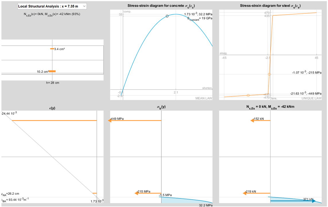
It is observed that, to reach the required curvature, the tensile reinforcement has extended deep into the plastic plateau, while the concrete has also approached its ultimate compression limit.
There is therefore a mechanical limit to redistribution, beyond which steel or concrete reaches its limits, and the support section can no longer deform sufficiently to maintain beam continuity: deformations become incompatible, and the plastic hinge fails.
Support reloading strategies and reinforcement optimization
We have just examined the case of significant redistribution of moments towards the spans.
It is also possible to adopt an opposite strategy consisting in increasing reinforcement at supports and reducing it in the spans. In the same manner, plastic zones then develop, this time primarily within the spans, and the exact moment distribution evolves according to the effective stiffnesses obtained along the beam after plastification, until the support moment matches the targeted value under ultimate loading conditions.
In general, the greater the redistribution of the support moment, the lower the amount of reinforcement required (in this study, the total decreases from 17HA12 to 12HA12 from left to right).
This observation also applies when dealing with different loading scenarios between spans. The use of redistribution leads to more compact bar cut-off diagrams and optimization of reinforcement quantities in structures.
For this reason, reinforcement strategies are generally oriented more towards redistribution rather than increasing support moments.
“French” practice of moment redistribution at SLS
Historically, French design rules prior to Eurocodes, notably BAEL, made extensive use of the concept of concrete adaptation to justify significant moment redistributions, both at ULS and at SLS.
With the introduction of EC2, new theoretical tools make it possible to better characterize and regulate the mechanisms of cracking, plastification, and redistribution.
In France, certain practices have nevertheless been maintained, notably to ensure continuity of usage and preserve accumulated experience. French recommendations thus allow, in certain cases, the application of moment redistributions at SLS in proportions comparable to those used at ULS.
Non-linear analysis provides additional insight into these phenomena. In the studied cases, it shows that the redistributions observed at SLS may differ significantly from those assumed in simplified approaches.
These observations encourage a case-by-case review of the assumptions used for evaluating internal forces at SLS, particularly when stress levels or crack widths represent a sensitive issue in the project.
What are the consequences of overestimating moment redistribution at supports at SLS?
If we consider the overall EC2 framework, an overestimation of redistribution at SLS leads to an underestimation of cracking at supports (i.e. an underestimation of tensile stresses in top reinforcement and crack widths), and, in some cases, to plastification of top reinforcement under service conditions.
Non-linear analysis according to EC2 shows, for example, that when sections are designed based on a structural analysis such that Ma,ULS = 0.6M0, meaning that 0.6A0 is provided at the support, the characteristic SLS moment is not 0.6M0 but rather Ma,SLS = 0.83M0.
By redistributing the moment at SLS in the same proportion as at ULS, the moment is therefore underestimated by about 30%, as are the stresses in the tensile reinforcement at the intermediate support.
Linear-elastic analyses for practical design
Use of non-linear analysis
In practical terms, the engineer may design continuous beams using a non-linear analysis according to EC2 §5.7, as previously illustrated. The process then consists of testing solutions in an iterative manner until the proposed design meets all the design criteria:
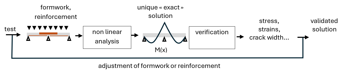
This process is also used in the general design method for slender columns (EC2 §5.8.6).
Simplified EC2 analysis methods: linear-elastic analysis
However, in the case of beams, internal forces N, T, and M may vary significantly along the length, and consequently so does reinforcement.
It is therefore not straightforward to define, at first, a “trial” reinforcement distribution without having first calculated the internal forces N, T, M.
EC2 provides a solution to this circular problem by explicitly allowing simplified and more direct calculation methods, admitting an approximate determination of internal forces, while neglecting the influence of reinforcement distribution.
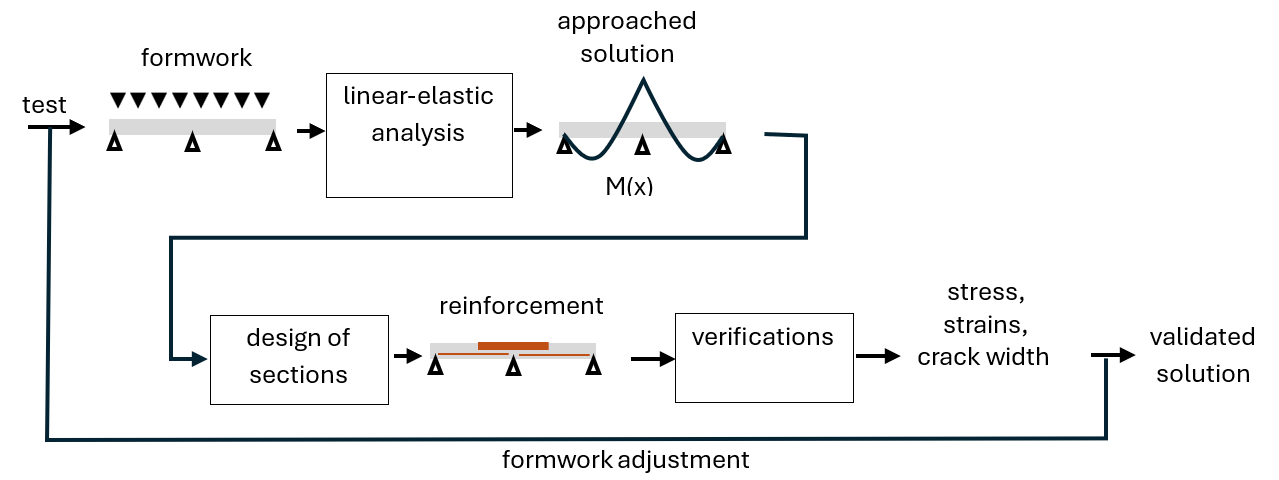
These analyses are linear-elastic, which greatly simplifies the numerical computation, allowing both the use of 3D finite element models for complex geometries and standard strength of materials formulas for simple geometries.
Moreover, by assumption, since reinforcement is considered not to influence the distribution of internal forces, the reinforcement is determined explicitly after the structural analysis, avoiding any need for iterative procedures in the search for a solution.
However, the assumption of independence between internal forces and reinforcement remains a strong assumption that “stiffens” the design approach, eliminating the optimization potential offered by concrete adaptation.
Simplified EC2 analysis methods: Plastic analysis
To overcome this limitation, EC2 proposes an “enhanced” version of linear-elastic analysis, consisting in formalizing the concept of a plastic hinge, introduced previously, so that it can be used before the reinforcement design phase.
In practice, the introduction of these hinges will limit the bending moment that can be transmitted at ULS to a value Mrot: as loading cases evolve, when linear-elastic analysis leads to a value greater than Mrot, continuity at the section is effectively lost, the moment is capped at Mrot, the beam loses one degree of freedom, and the portion of moment that is no longer balanced is redistributed to adjacent parts of the beam.
This method, referred to as plastic analysis according to EC2 §5.6, makes it possible to reintroduce in a simplified manner, within a linear-elastic analysis, the redistribution phenomenon highlighted previously in non-linear analysis.
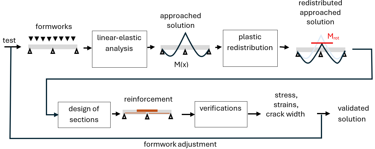
As previously discussed, it is advantageous to systematically introduce these plastic hinges at supports in order to redistribute moments towards the spans and “compress” bar cut-off diagrams to optimize reinforcement in a structure. The linear-elastic analysis with limited moment redistribution – EC2 §5.5 corresponds to this practice.
A slab on four supports: linear-elastic analysis vs non-linear analysis
In this section, we carry out a comparative analysis between the results provided by a simplified structural analysis, of the linear-elastic type, possibly with redistribution, and those provided by a non-linear structural analysis.
We consider again the example of the 28 cm slab, now assumed to consist of three spans of 7.50 m, under different possible loading situations, at ULS and SLS.
The system under consideration is fully symmetrical.
The tables reproduce simulation results for:
- Mt: moment in the end span
- Ma: support moment at the internal support adjacent to the end
Linear-elastic analysis vs non-linear analysis
It is assumed that the linear-elastic analysis has led to the following slab reinforcement:
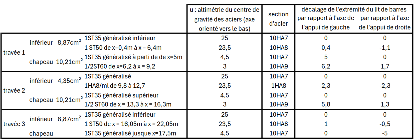
Based on this reinforcement, we successively examine the ULS internal forces obtained from a linear-elastic analysis and then from a non-linear analysis, for the various loading cases to be considered.
The results are summarized in the table below:
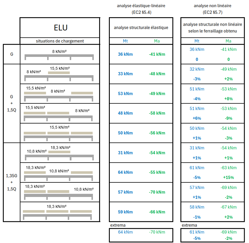
It can be observed that the extrema obtained from the linear-elastic analysis are very close to those obtained from the non-linear analysis taking into account the selected reinforcement: the results are satisfactory.
The main difference occurs in the 3rd and 7th loading cases. In these cases, the spans undergo greater plastification (reaching 100% utilization), while the supports are at about 90%. The non-linear analysis then shows a slight increase in support moments and a reduction in span moments.
We can now compare the results for SLS loading cases:
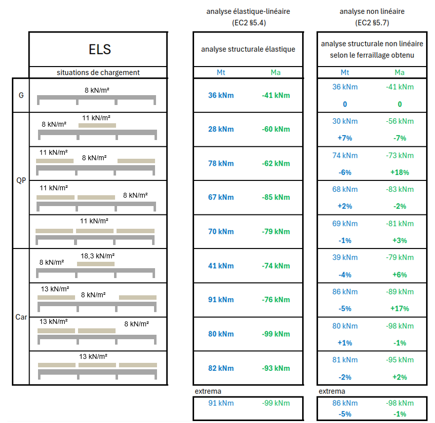
The results are satisfactory at SLS, with the same observations as at ULS.
Linear-elastic analysis with redistribution vs non-linear analysis
This time, we perform a structural analysis assuming a 30% redistribution of the maximum support moment, both at SLS and ULS.
For this new analysis, the following reinforcement layout is adopted:
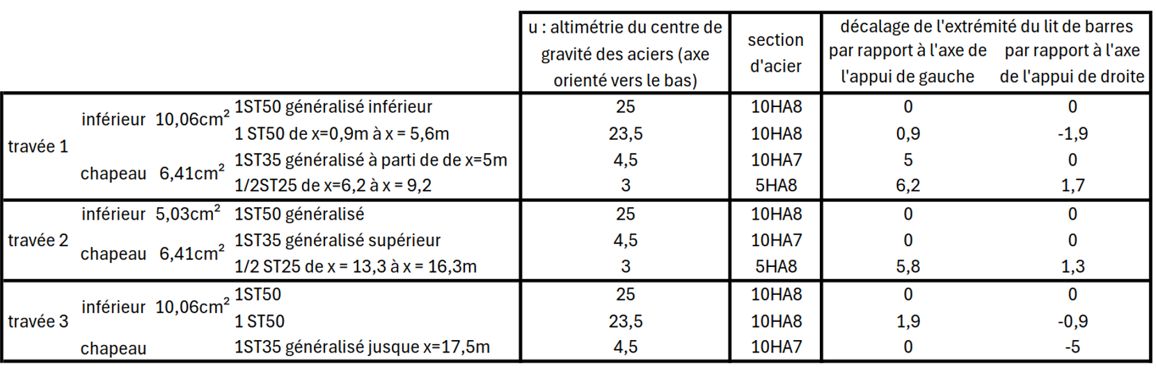
The top reinforcement at the support adjacent to the end span is now 6.41 cm²/m (1ST35 + 1ST25) instead of 10.21 cm²/m (1ST35 + 1ST60) previously.
According to the linear-elastic structural analysis, the maximum ultimate support moment was 99 kNm. Due to the redistribution assumption, this value is reduced by 30%, and the provided reinforcement is therefore now capable of resisting 70 kNm.
Each loading case is then studied considering that:
- if the linear-elastic analysis gives a support moment < 70 kNm, the moment is not redistributed (no plastification at the support),
- if the linear-elastic analysis gives a support moment > 70 kNm, the support moment is capped at 70 kNm, and the excess is redistributed to adjacent spans (plastification occurs and a plastic hinge forms).
The table below illustrates this redistribution procedure based on linear-elastic results:
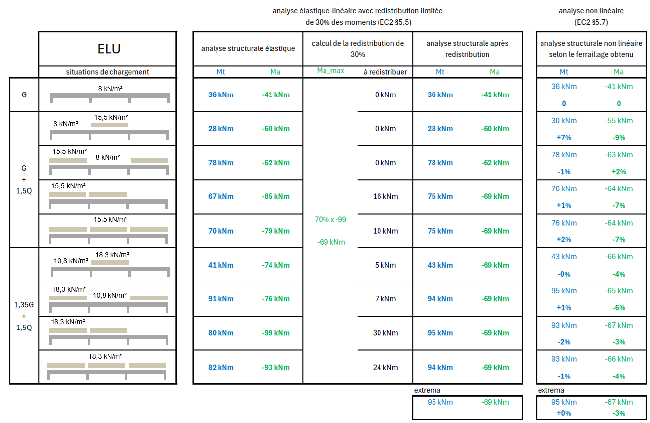
As in the case “without redistribution”, the extreme internal forces obtained from a linear-elastic ULS analysis with 30% redistribution match well with those obtained from the non-linear analysis accounting for the new reinforcement. Overall, the comparison is again satisfactory.
We now perform the SLS analysis, while keeping the previously determined reinforcement:
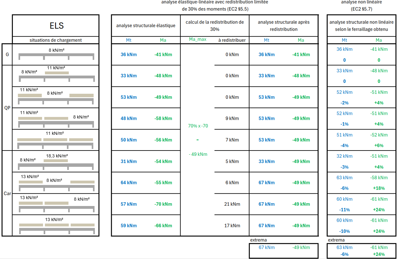
This time, the results are not satisfactory: linear-elastic analysis with 30% redistribution at SLS does not give results consistent with non-linear analysis.
In the loading case that maximizes the support moment, it reaches 61 kNm instead of 49 kNm, corresponding to a redistribution of 13% rather than 30%.
More precisely, in the final characteristic SLS loading case (all spans loaded), the local analysis of the support section gives the following results:
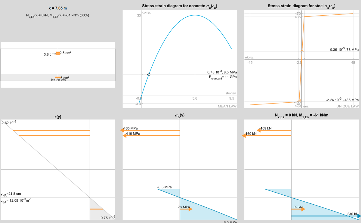
The following points can be observed:
- stresses in the reinforcement are close to yielding and exceed the allowable SLS characteristic stresses (0.8fyk),
- the flexibility of the support section, resulting from cracking, is insufficient to produce significant moment redistribution, and the support moment (61 kNm) remains close to the linear-elastic value (66 kNm).
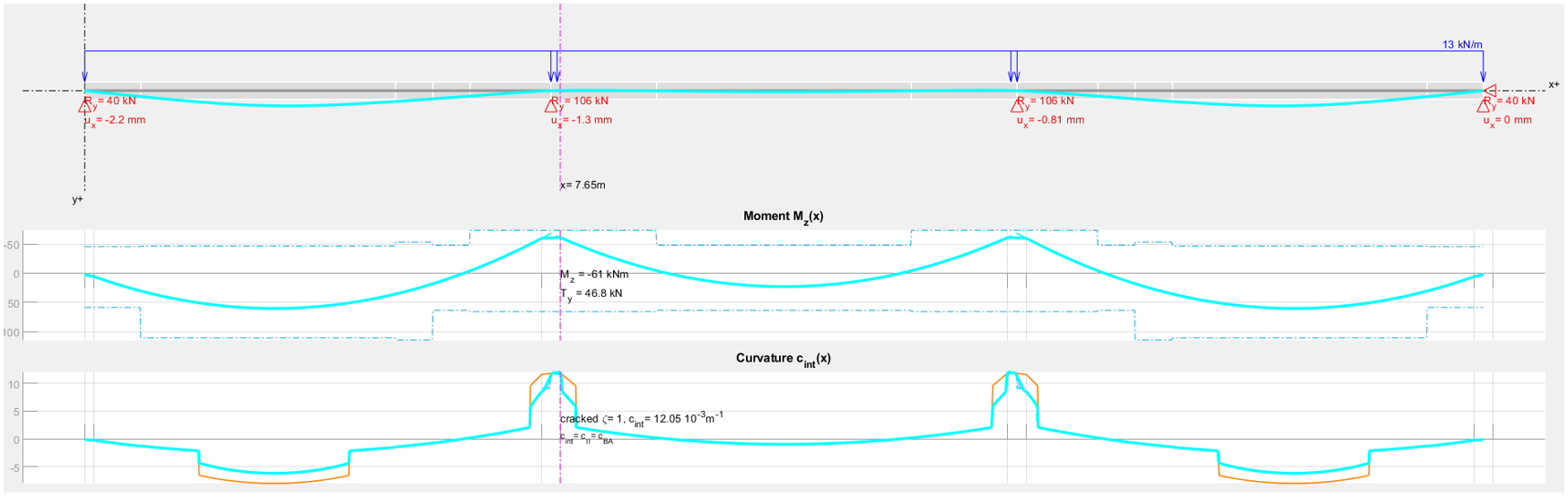
This example highlights, in another way, the limits and conditions of applicability of moment redistribution at SLS.
Conclusion
This entire study confirms the relevance and validity of linear-elastic methods, with limited redistribution, and plastic methods proposed by EC2, which today form the basis of practical structural design in the profession.
It also shows that the use of non-linear analyses can provide additional insight into certain mechanisms, particularly for a better understanding of redistribution phenomena, especially when designs or service conditions present increased sensitivity.
These approaches enhance the understanding of structural behaviour and help to inform design and modelling choices.
The article also addresses issues related to redistribution at SLS, within the framework of existing practices and the general principles of EC2, highlighting the importance of consistency between calculation models and feedback from experience.
These topics remain open to discussion and feedback.
